Automatic centrifuge, pre-analysis system with automatic centrifuge and the control techniques of that system

a technology of automatic centrifuge and pre-analysis system, which is applied in the direction of material analysis, centrifuges, instruments, etc., can solve the problem that the centrifuge operation cannot be normally performed, and achieve the effect of minimizing the delay of abnormal specimens

Active Publication Date: 2013-10-24
HITACHI HIGH-TECH CORP
View PDF13 Cites 8 Cited by
  • Summary
  • Abstract
  • Description
  • Claims
  • Application Information

AI Technical Summary

Benefits of technology

[0037]A weight of a specimen loaded into a specimen-test automation system is correctly recognized at a prior stage to conveying to a specimen processing unit, so that normal centrifugal operation can be performed, and result report delay of an abnormal specimen can be minimized.
[0038]FIG. 1 is a drawing illustrating a setting order of specimen containers at an adaptor;
[0039]FIG. 2 is an overall diagram according to a specimen-rack conveyor line unit of a specimen-test pre-analysis system;
[0040]FIG. 3 is a perspective view of an overall configuration of an automatic centrifugal processing unit;
[0041]FIG. 4 is a perspective view obtained by removing an upper portion of the automatic centrifugal processing unit;
[0042]FIG. 5 is a processing flow chart for setting specimens at adaptors of an automatic centrifuge;

Problems solved by technology

Therefore, if weights of the buckets arranged at the pair of buckets are significantly different from each other, the rotation abnormality of the rotor is caused, and the centrifugal operation cannot be normally performed.

Method used


Image

  • Automatic centrifuge, pre-analysis system with automatic centrifuge and the control techniques of that system
  • Automatic centrifuge, pre-analysis system with automatic centrifuge and the control techniques of that system
  • Automatic centrifuge, pre-analysis system with automatic centrifuge and the control techniques of that system

Examples


first embodiment

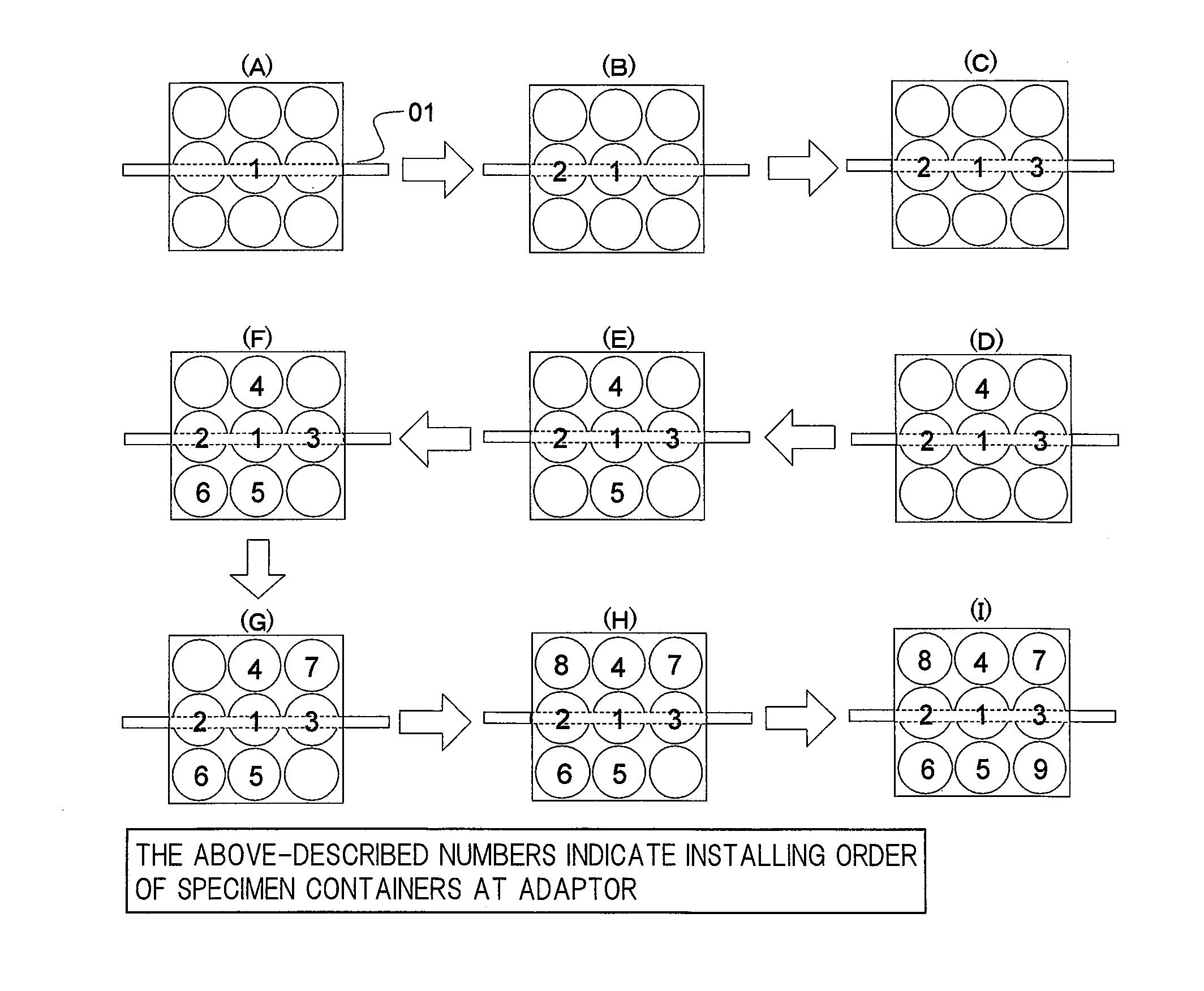
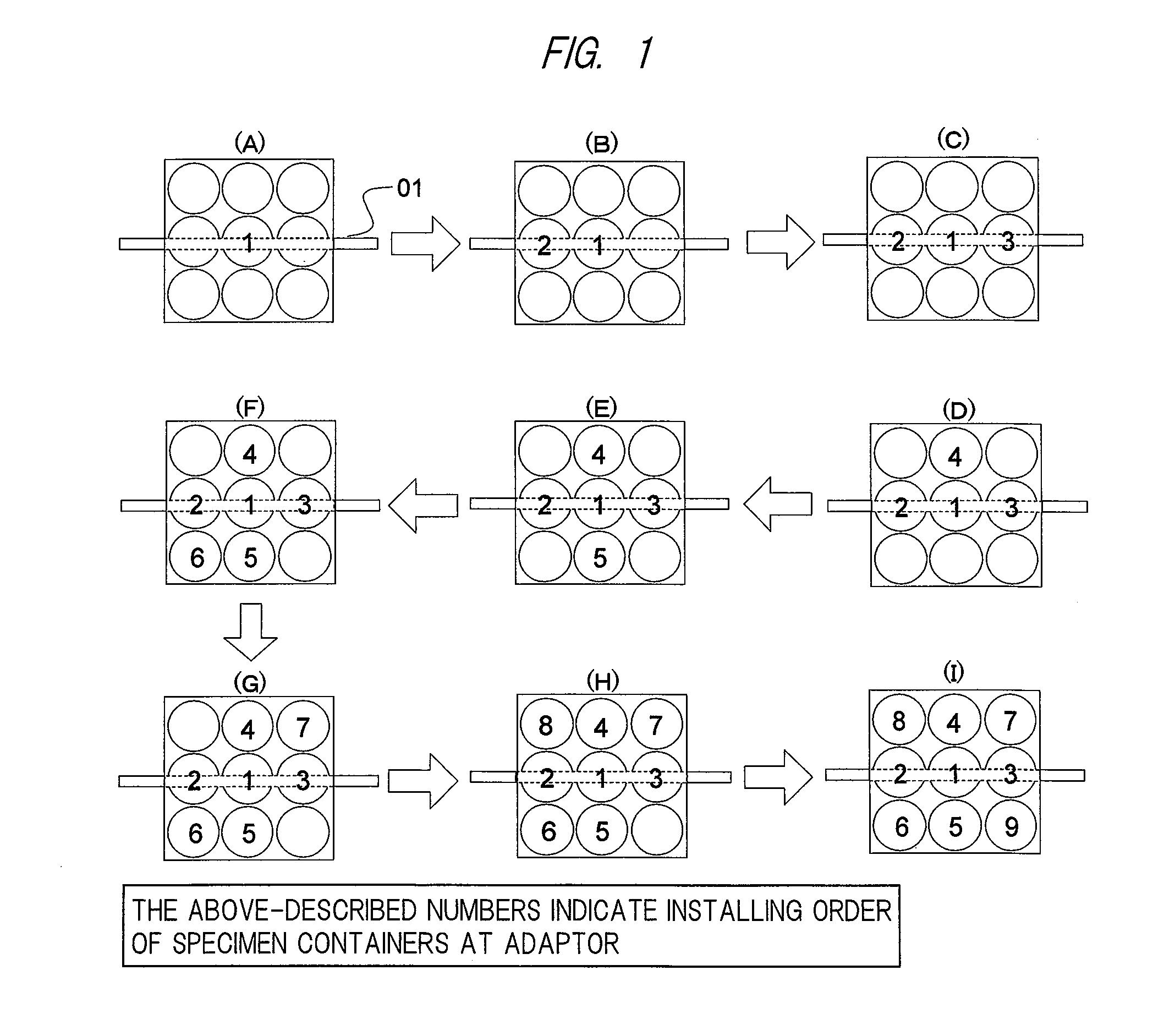
[0064]FIG. 5 illustrates a process flow from the loading of the specimens to the setting of the specimens at the adaptors 210 of the automatic centrifuge.

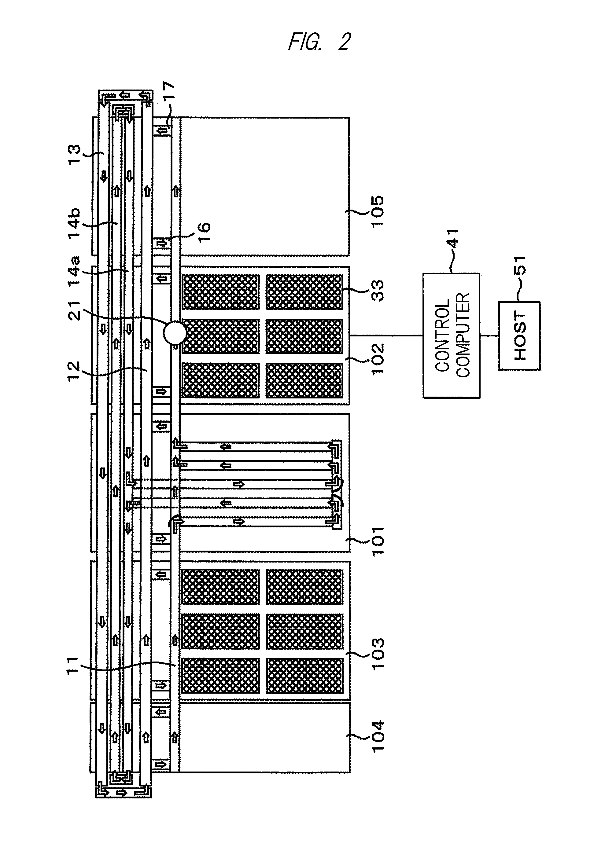
[0065]For the specimens loaded from the loading module 102, the weight of the specimen container 32 is measured while being set in the holder 31 by a specimen-container weight-measurement mechanism 20 on the main conveyor line 11 in a step 501, and the specimen container is conveyed to the automatic centrifuge in a step 502. The specimen chuck mechanism 204 stands by without setting the specimen container 32 at the adaptor 210 until the number of the specimen containers 32 conveyed to the automatic centrifuge reaches the maximum number of specimens which can be subjected to the centrifugal processing at once (in a step 503).

[0066]In order to achieve efficient processing, even if the number does not reach the maximum number of specimens which can be subjected to the centrifugal operation at once but if the next specimen container is...

second embodiment

[0078]A process flow according to another embodiment from the loading of the specimens to the setting of the specimens at the adaptors 210 of the automatic centrifuge will be explained.

[0079]Here, a case that two automatic centrifuges each of which is one of the pre-analysis units are connected to the pre-analysis system will be explained as an example. Hereinafter, the automatic centrifuges will be referred to as an automatic centrifuge 1 and an automatic centrifuge 2, respectively.

[0080]After the bar-code information of the specimen is read in the loading module 102, the weight of the specimen container 32 is measured by the specimen-container weight-measurement mechanism 20 on the main conveyor line 11 while being set at the holder 31. The present weight information is transmitted to the control computer 41 together with the ID of the holder at which the specimen is set.

[0081]From the specimen weight, the control computer 41 determines which adaptor 210 the specimen is to be set ...

third embodiment

[0087]Next, a procedure according to still another embodiment from the loading of the specimen, then, the recognition of the abnormal specimen, until the collection of the specimen will be explained.

[0088]Prior to the start of the pre-analysis processing, the normal-specimen weight range values are set. FIG. 7 illustrates an example of a setting screen of the normal-specimen weight range values of each specimen container. In FIG. 7, the minimum weight and the maximum weight are set for each test tube container. Also, in an item “Others” in FIG. 7, a value used when a specimen container whose shape cannot be determined by a shape recognition mechanism of the specimen container 32 is loaded into the system is set.

[0089]When the specimen container 32 is loaded by the loading module 102, the specimen container 32 is transferred to the holder 31, and the conveying is started. For the specimen container 32, the container shape is recognized by means for recognizing the specimen container ...


PUM

PropertyMeasurementUnit
weightaaaaaaaaaa
weightaaaaaaaaaa
gravityaaaaaaaaaa

Abstract

A determination mechanism which obtains information about the weight of the specimen housed in the specimen container is arranged on a conveyor line for connecting between a loading module and an automatic centrifugal unit, the specimens are held without being installed at an adaptor until the number of the specimens which can be subjected to a centrifugal processing at once by the automatic centrifugal unit arrives, and the specimens are installed after the arrival in an order from a heavier specimen at the adaptors to be paired, which are installed at the symmetric positions to each other across the rotation central axis. Also, the specimen is installed at the gravity-center position of the adaptor first, and the subsequent specimens are installed from the inner side at the point-symmetric positions to each other across the gravity-center position.

Description

TECHNICAL FIELD[0001]The present invention relates to an automatic centrifuge for performing centrifugal process to a specimen inside a pre-analysis system, and, more particularly, the present invention relates to a pre-analysis system, a specimen-test automation system, and control techniques of the systems capable of avoiding unbalanced operation due to a weight difference upon the centrifugal process.BACKGROUND ART[0002]In recent years, in the medical field, a labor-saving test operation has been promoted by introducing various automation devices. In tests in a hospital, test specimens of hospital inpatients and outpatients are collected in each department in the hospital, and are collectively processed in a test room. A test item for each specimen is transferred from a doctor to the test room by using an online information processing system, and a result of the test is reversely reported online from the test room to the doctor. Most of test items for blood and urine require pre-...

Claims


Application Information

Patent Timeline
Patent Type & Authority Applications(United States)
IPC IPC(8): G01N35/04
CPCG01N35/04B04B9/14B04B13/00B04B2011/046B04B9/146
Inventor YAGI, KENICHINODA, TAKAYUKIAKUTSU, MASASHI
Owner HITACHI HIGH-TECH CORP
Why Eureka
Try Eureka