Tray locking device of optical disc drive
- Summary
- Abstract
- Description
- Claims
- Application Information
AI Technical Summary
Benefits of technology
Problems solved by technology
Method used
Image
Examples
Embodiment Construction
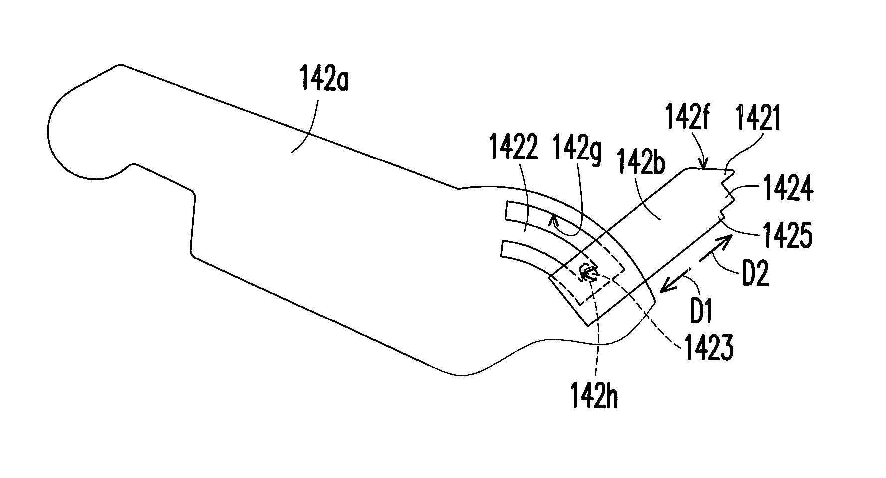
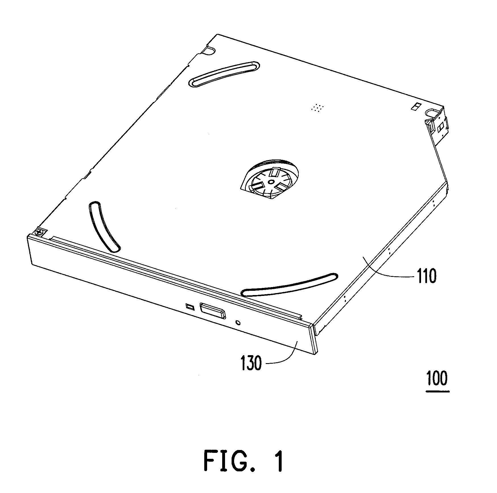
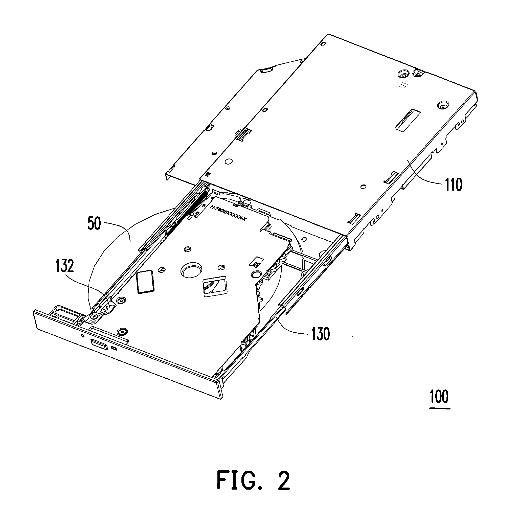
[0020]FIG. 1 is a schematic view showing a perspective view of an optical disc drive according to one embodiment of the present invention. FIG. 2 is a schematic view showing the tray is ejected from the optical disc drive of FIG. 1. FIG. 3 is a schematic view of the tray locking device of the optical disc drive of FIG. 1. Referring to FIG. 1 to FIG. 3, the optical disc drive 100 of the present embodiment includes a housing 110, an optical head 120, a tray 130, a lead screw 112 and a tray locking device 140. The optical head 120 is engaged with the lead screw 112. When the lead screw 112 rotates, the lead screw 112 drives the optical head 120 to move along the lead screw 112 relatively. The tray 130 is slidably disposed in the housing 110 and has a locking position (as shown in FIG. 1) and an ejecting position (as shown in FIG. 2).
[0021]The tray locking device 140 of the present embodiment includes a transmission assembly 142, a pushing member 144 and a latching hook 132. The latchin...
PUM
 Abstract
Description
Claims
Application Information
 - R&D
- Intellectual Property
- Life Sciences
- Materials
- Tech Scout
- Unparalleled Data Quality
- Higher Quality Content
- 60% Fewer Hallucinations
Browse by: Latest US Patents, China's latest patents, Technical Efficacy Thesaurus, Application Domain, Technology Topic, Popular Technical Reports.
© 2025 PatSnap. All rights reserved.Legal|Privacy policy|Modern Slavery Act Transparency Statement|Sitemap|About US| Contact US: help@patsnap.com


