Surface covering comprising laminate panels and an extraneous locking element

a technology of laminate panels and locking elements, applied in the field of surface coverings, can solve the problems of instability at the interconnection zone where three connected panels are located, the corners of the connected panels cannot be locked, etc., and achieve the effects of reducing friction, reducing the friction of insertion, and reducing the friction

Active Publication Date: 2013-10-31
XYLO TECH AG
View PDF34 Cites 48 Cited by
  • Summary
  • Abstract
  • Description
  • Claims
  • Application Information

AI Technical Summary

Benefits of technology

[0029]The invention also relates to an extraneous locking element for the locking of at least two flooring panels. This element, which preferably can be used in connection with a surface covering as described above, is especially advantageous in that it can reduce the problems associated with insertion of the elements caused by friction. Friction can be in particular problematic if during assembly of a surface covering it becomes necessary to disassemble and reassemble panels. Further, it can become problematic if the surface covering has to be completely disassembles e.g. for reconstruction purposes or the like. In addition, upon insertion of the extraneous locking element into the channel friction hampers even the first assembly process of the surface covering.
[0030]To reduce said friction, according to the invention, the extraneous locking element is an essentially bar-shaped element with an essentially rectangular cross section, wherein at least one outer surface of the extraneous locking element is provided with a structure to reduce friction upon insertion. In a preferred embodiment, the structure comprises wave-shaped protrusions. In a further preferred embodiment, the structure comprises at least two protruding ribs or fins extending in the longitudinal direction of the extraneous locking element. The ribs can be provided in addition or alternatively to the wave-shaped protrusions, however the structure is provided such that the total area of a contact surface, i.e. the area of the surface of the extraneous locking element which is in contact with the channel when the extraneous locking element is inserted into the channel is reduced as compared to a surface without this structure.
[0031]To further facilitate the insertion of the extraneous locking element into the channel, preferably an end portion of the extraneous locking element is tapered towards a free end of the extraneous locking element. Alternatively, in a preferred embodiment the extraneous locking element is provided with beveled edges to facilitate insertion of the extraneous locking element. Preferably, an end portion of the extraneous locking element has a conical shape which is tapered towards a free end of the extraneous locking element.
[0032]In a preferred embodiment, the ratio between the height of the side edge of the extraneous locking element and the width of the upper edge of the extraneous locking element is in between 0.1 and 0.6, more preferably in between 0.15 and 0.55, even more preferably in between 0.2 and 0.5, yet even more preferably in between 0.25 and 0.45, and most preferably in between 0.3 and 0.4. This ratio is chosen to allow for optimal insertion of the extraneous locking element into the channel while offering at the same time sufficient mechanical rigidity with most suitable materials. Further, the effective thickness deff of the extraneous locking element is preferably in between 1 mm to 5 mm, more preferably in between 1.3 mm to 3 mm, even more preferably in between 1.35 mm to 2 mm, and most preferably in between 1.4 mm to 1.5 mm. Further, this effective thickness deff of the extraneous locking element is preferably chosen such that a portion of the extraneous locking element which extends into the groove of a panel is wedged, i.e. clamped, in between the lower lip contact portion and the upper lip contact portion.

Problems solved by technology

All the known solutions have in common that they only provide a secure connection at the transverse sides, however, the corners of the connected panels cannot be locked thereby.
A generally known difficulty which can arise in the case of surface coverings consisting of panels as described above is instability at the interconnection zones where three connected panels met.

Method used


Image

  • Surface covering comprising laminate panels and an extraneous locking element
  • Surface covering comprising laminate panels and an extraneous locking element
  • Surface covering comprising laminate panels and an extraneous locking element

Examples


Embodiment Construction

[0035]In the following, the invention is described exemplarily with reference to the enclosed figures in which

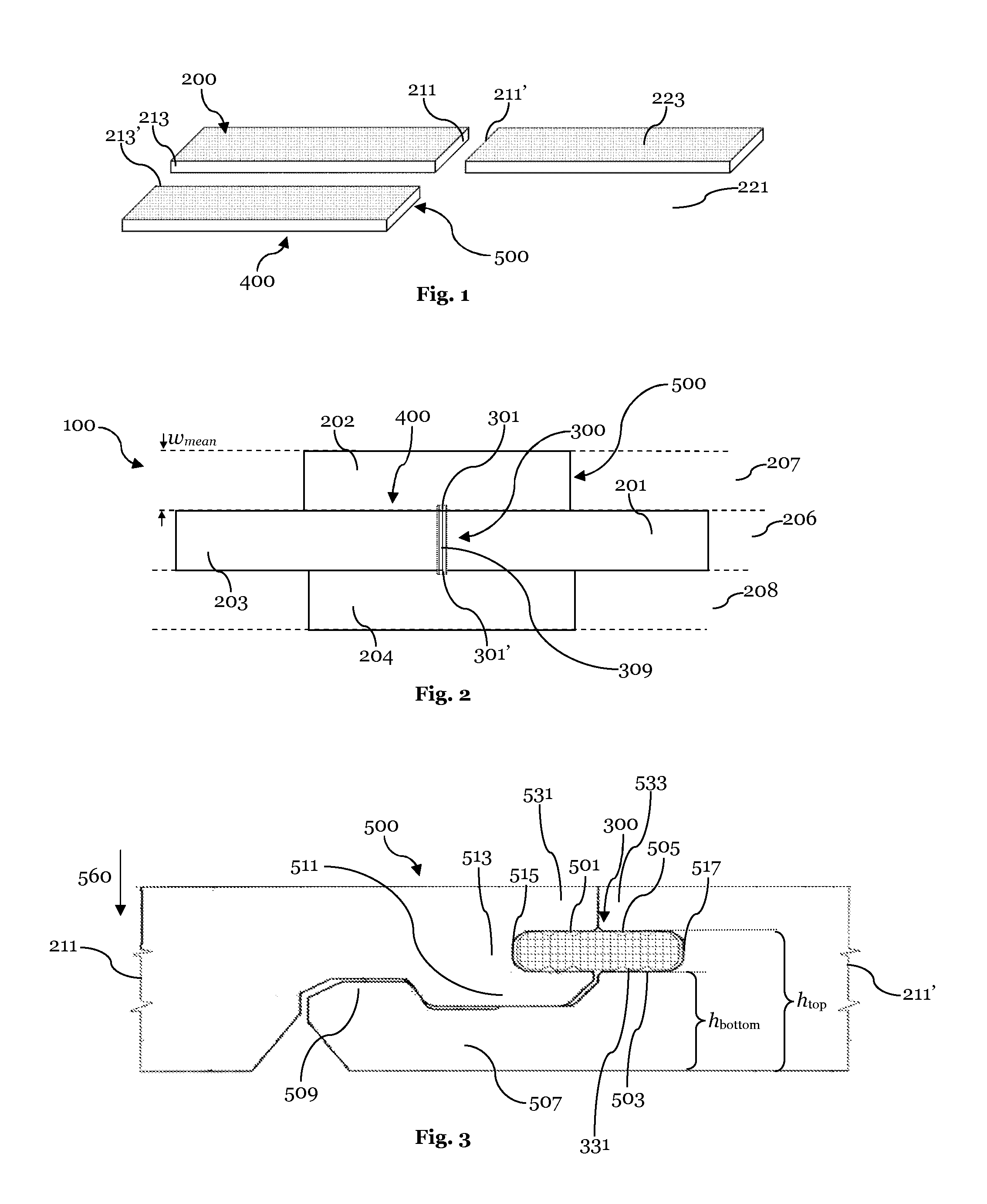
[0036]FIG. 1 shows a schematic view of three panels laid in a common plane, being not connected to each other;

[0037]FIG. 2 is a schematic top view of a surface covering, whereby four panels are exemplarily shown connected to each other;

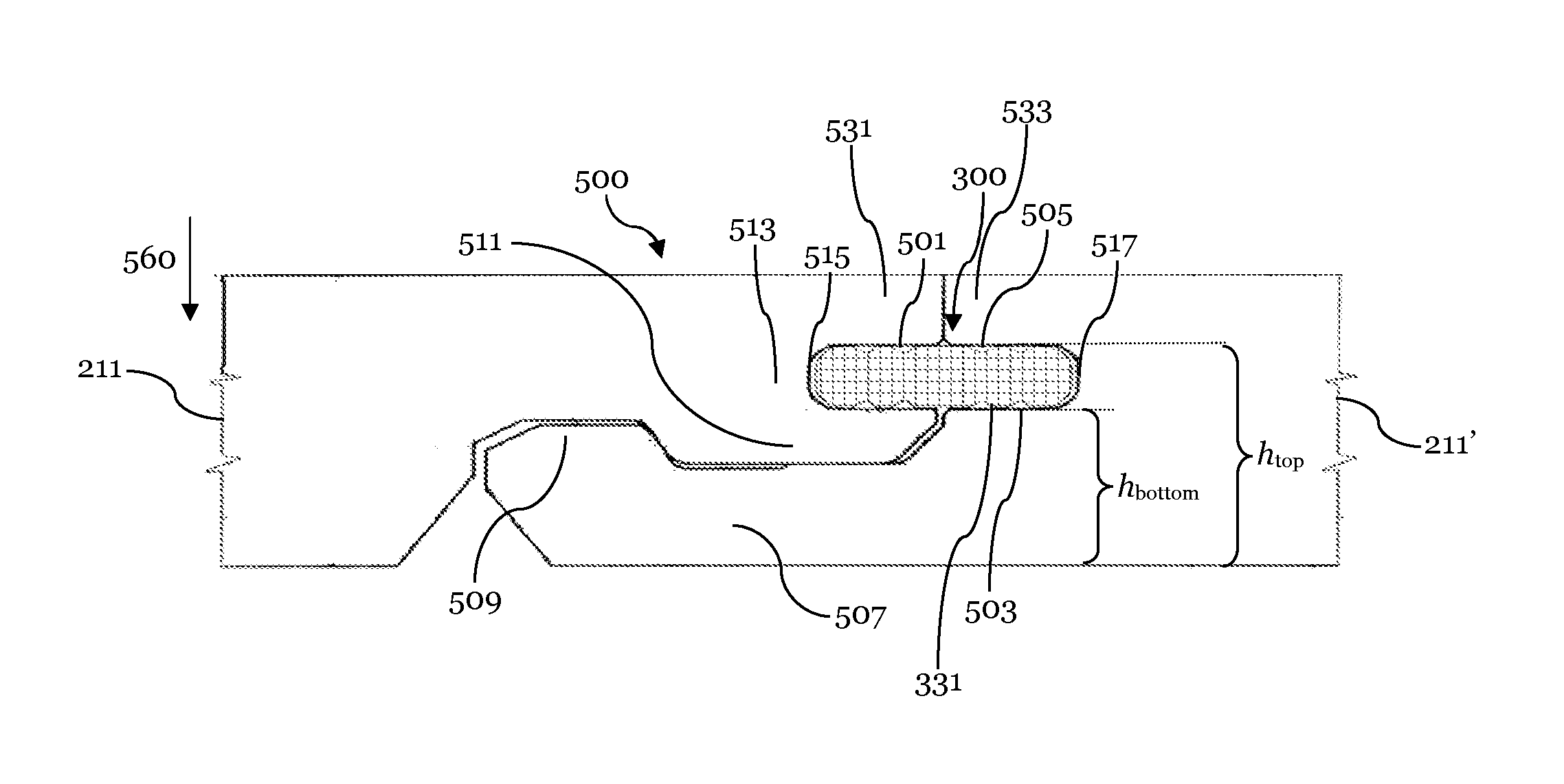
[0038]FIG. 3 shows a cross section of transverse coupling means in coupled condition, whereby an extraneous locking element is inserted into a channel formed by the transverse coupling means;

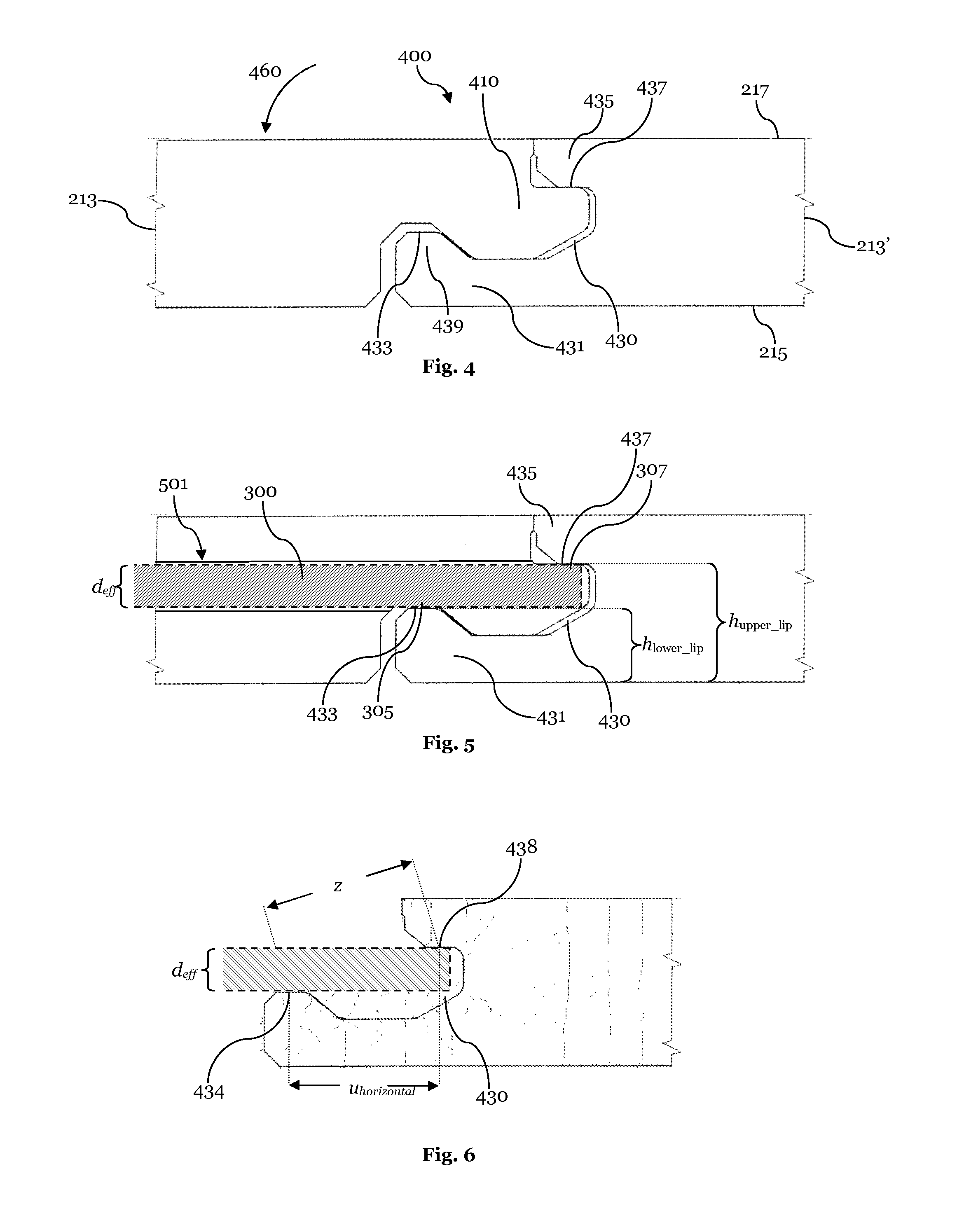
[0039]FIG. 4 shows a cross section of longitudinal coupling means in coupled condition;

[0040]FIG. 5 is a schematic cross sectional view showing the longitudinal coupling means of FIG. 4 in coupled condition, whereby an extraneous locking element is shown inserted into a groove of the longitudinal coupling means;

[0041]FIG. 6 shows the groove of FIG. 5 and the inserted extraneous locking element of FIG. 5;

[0042]FIG. 7 shows details of the groove of FIGS. 5 a...


PUM

PropertyMeasurementUnit
heightaaaaaaaaaa
heightaaaaaaaaaa
heightaaaaaaaaaa

Abstract

The present invention relates to a surface covering (100) comprising panels (200) and at least one extraneous locking element (300). The panels (200) are provided with respective longitudinal and transverse coupling means (400, 500) which are adapted to connect similar panels (200) at corresponding adjacent edges (211, 211′, 213, 213′). The transverse coupling means (500) are adapted to form a channel (501) in coupled condition which is adapted to receive the extraneous locking element (300). When inserted into the channel (501) formed by the transverse coupling means (500) of panels (200) in a first row (206), the extraneous locking element is adapted to extend at least partially into the groove (430) of an adjacent parallel panel in the second row (207), such that a lower surface (305) of the extraneous locking element (300) is in contact with a lower lip contact portion (433), and the upper surface (307) of the extraneous locking element (300) is in contact with an upper lip contact portion (437).

Description

1. FIELD OF THE INVENTION[0001]The present invention relates to a surface covering, in particular to a floor, ceiling or wall covering, comprising panels and an extraneous locking element as well as to a method of assembling the same.2. TECHNICAL BACKGROUND[0002]A variety of different kinds of surface coverings, in particular floor, ceiling or wall coverings are known in the art. In particular for interior applications, wooden panels or panels having the appearance of wood are very popular. In the recent years laminate panels have been developed in particular to be used as flooring panels reproducing the appearance of various kinds of different wood panels.[0003]In general, laminate panels comprise a base or carrier board of MDF, HDF or OSB which is provided on one side with a decor for example to reproduce the appearance of a real wood panel. This decor can be provided either as a printed paper layer or a veneer, or the decor can be directly printed onto the carrier board. Often, t...

Claims


Application Information

Patent Timeline
Patent Type & Authority Applications(United States)
IPC IPC(8): E04F15/02E04F13/08
CPCE04F15/02038E04F13/0873E04F2201/0138E04F2201/0153E04F2201/0523E04F2201/0541E04F2201/057E04F2201/0576E04F2201/0588E04F2201/0511E04F13/0894E04F15/02
Inventor DOHRING, DIETERGRUNDEL, MICHAEL
Owner XYLO TECH AG
Why Eureka
Try Eureka