
Geothermal system

a geothermal system and geothermal heating technology, applied in the field of geothermal heating and cooling, can solve the problems of increasing energy costs and achieve the effects of reducing the chance of contaminating the surrounding soil, reducing the chance of contamination, and being easy to install in the field

Inactive Publication Date: 2013-10-31
GEOENERGY ENTERPRISES
View PDF6 Cites 2 Cited by
  • Summary
  • Abstract
  • Description
  • Claims
  • Application Information

AI Technical Summary

Benefits of technology

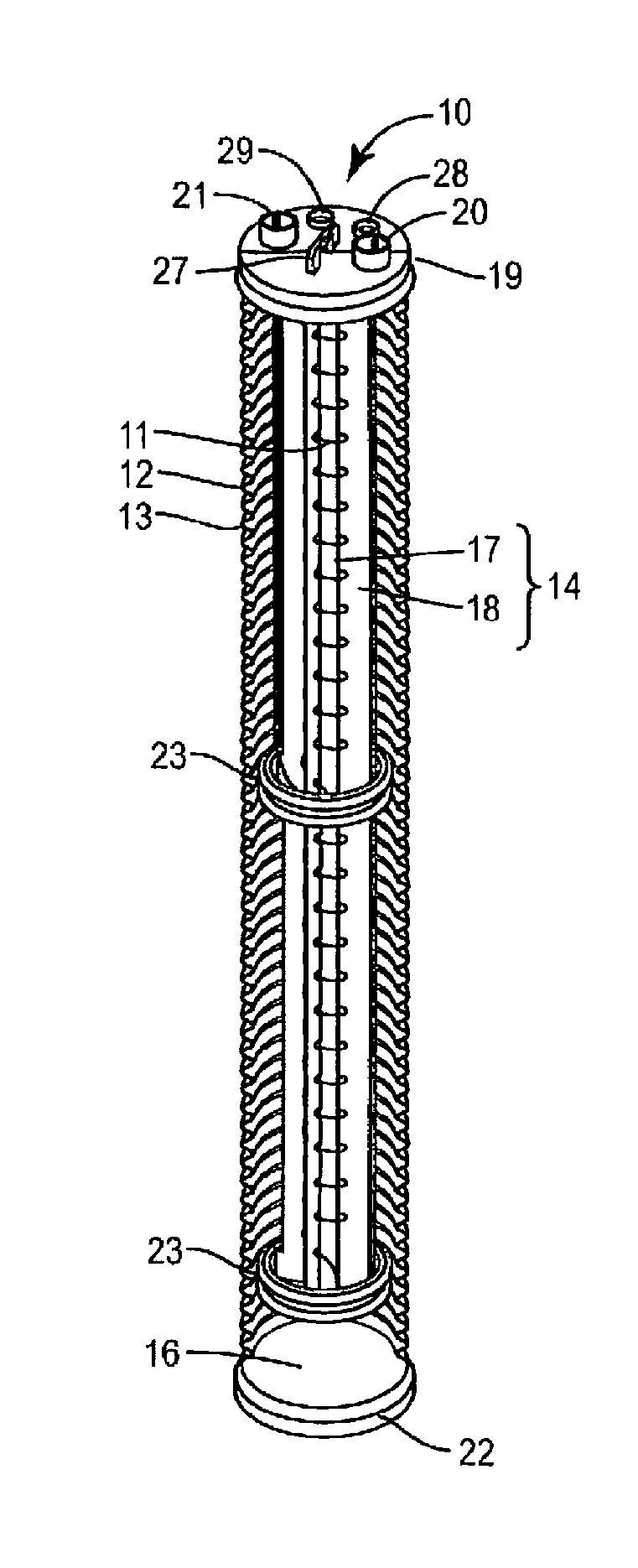
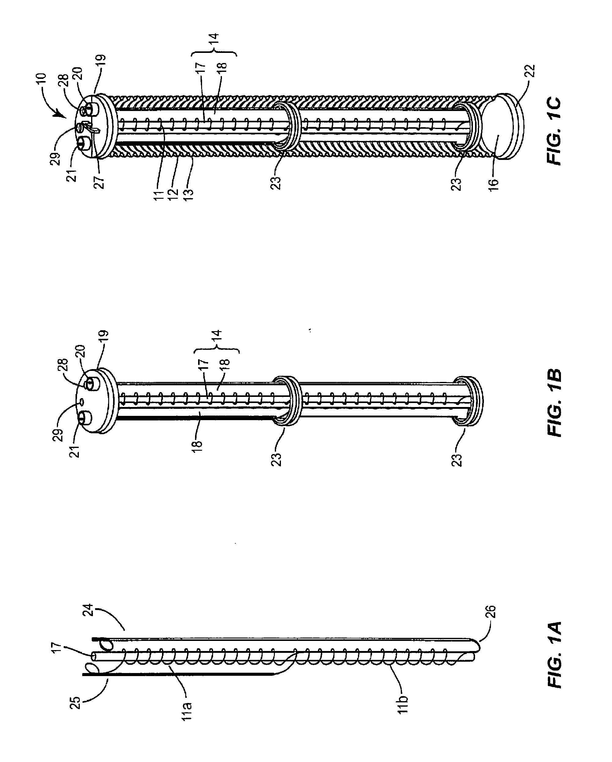
The present invention provides an improved geothermal system that includes a geothermal column that is easy to install and has enhanced heat transfer qualities. The column uses an antifreeze-free liquid to transfer heat in a vertical orientation, which requires less digging and has low impact on the environment. The system also includes a pre-fabricated unit that can be installed quickly and easily with little labor. The hollow tube construction allows for efficient heat transfer without the need for antifreeze, reducing the chance of contaminating the surrounding soil. The new factory assembled unit has a superior degree of heat transfer with reduced hot or cold spots.

Problems solved by technology

Geothermal energy is becoming more and more important in the global environment as the supply of fossil fuels diminish, the demand for energy increases, control and demands from oil producing companies are at issue and the costs of energy continues to rise.

Method used


Image

  • Geothermal system
  • Geothermal system
  • Geothermal system

Examples


Embodiment Construction

[0018]The present invention may be understood more readily by reference to the following detailed description of the invention taken in connection with the accompanying figures, which form a part of this disclosure. It is to be understood that this invention is not limited to the specific devices, methods, conditions or parameters described and / or shown herein, and that the terminology used herein is for the purpose of describing particular embodiments by way of example only and is not intended to be limiting of the claimed invention.

[0019]As used in the specification and including the appended claims, the singular forms “a,”“an,” and “the” include the plural, and reference to a particular numerical value includes at least that particular value, unless the context clearly dictates otherwise.

[0020]Ranges may be expressed herein as from “about” or “approximately” one particular value and / or to “about” or “approximately” another particular value. When such a range is expressed, another...


PUM


Abstract

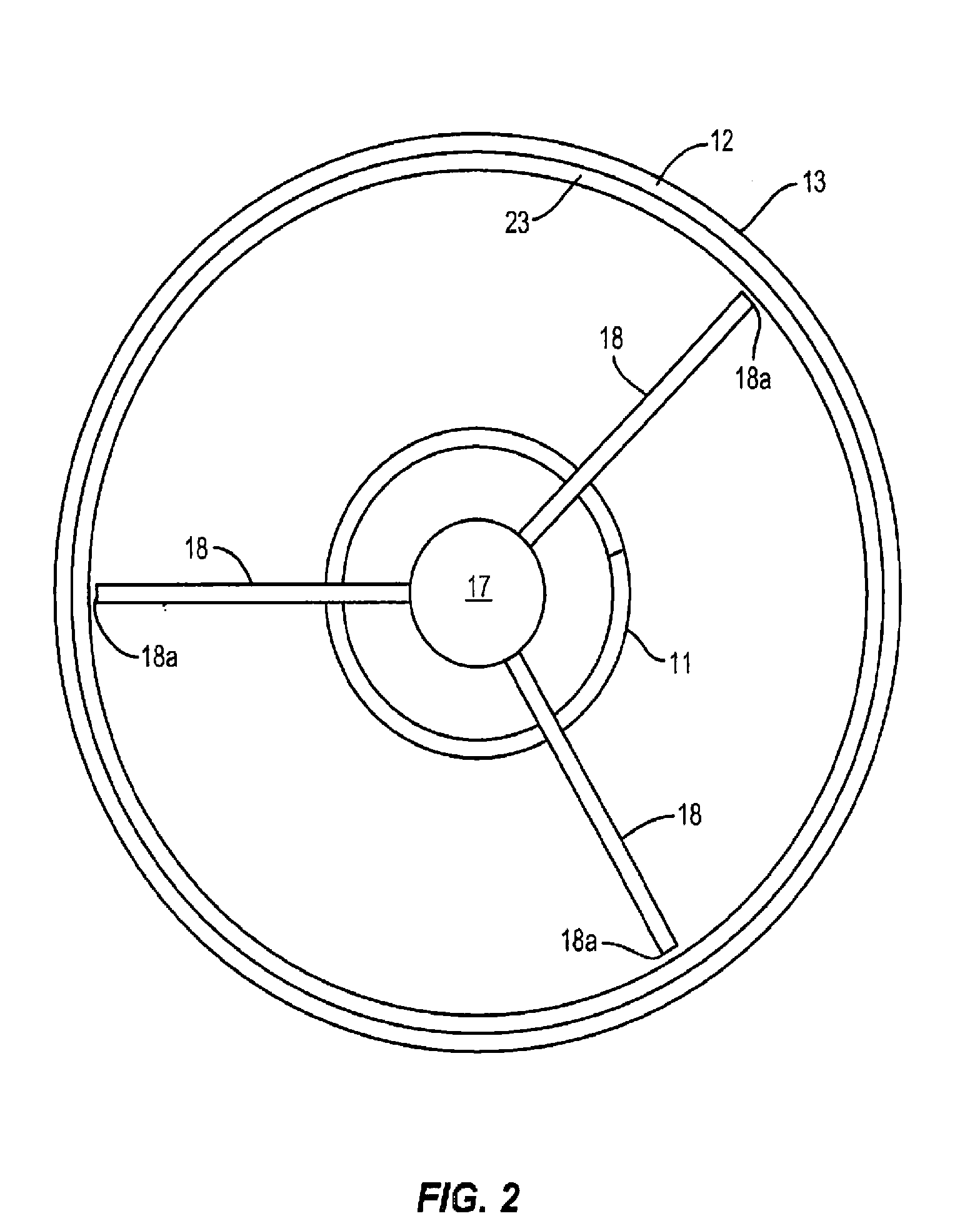
A geothermal system, comprising at least one geothermal column, comprising at least one spirally wound refrigeration coil configured to communicate with a heat pump compressor; a hollow tube having an outer wall of diameter substantially greater than that of said at least one spirally wound refrigeration coil and positioned so as to surround said at least one spirally wound refrigeration coil, said outer wall having a substantially rigid configuration such that said hollow tube maintains its shape; and a support member configured to retain a shape of said at least one spirally wound refrigeration coil and maintain a centrally located position of said at least one spirally wound refrigeration coil within said hollow tube; and a compressor section in communication with the at least one geothermal column and a climate system.

Description

CROSS REFERENCE TO RELATED APPLICATIONS[0001]The present application claims priority to U.S. Provisional application No. 61 / 410,053 filed Nov. 4, 2010, which is herein incorporated by reference in its entirety.FIELD OF THE INVENTION[0002]This invention relates generally to the field of geothermal heating and cooling, and more particularly to an improved heat transfer geothermal system that includes at least one geothermal column positioned within an earth mass for transfer of heat to and from the earth mass.BACKGROUND OF THE INVENTION[0003]Any publications or references discussed herein are presented to describe the background of the invention and to provide additional detail regarding its practice. Nothing herein is to be construed as an admission that the inventors are not entitled to antedate such disclosure by virtue of prior invention.[0004]Geothermal energy is becoming more and more important in the global environment as the supply of fossil fuels diminish, the demand for ener...

Claims


Application Information

Patent Timeline
IPC IPC(8): F24J3/08
CPCF24J3/08F24T10/13F24T10/30F25B30/06Y02E10/10
Inventor GENUNG, SHAWNPENACHIO, TONY
Owner GEOENERGY ENTERPRISES
Learn More