
Cable Locking System

a locking system and cable technology, applied in the field of cable locking systems, can solve the problems of shortening the life of the system, affecting the quality of the cable, and whitehill et al. does not teach a box including a first keyhole, so as to achieve the effect of easy disassembly, quick and easy installation, and quick and easy connection

Inactive Publication Date: 2009-07-16
DENMARK MARVIN ALBERT
View PDF13 Cites 2 Cited by
  • Summary
  • Abstract
  • Description
  • Claims
  • Application Information

AI Technical Summary

Benefits of technology

[0017]The cable locking system can be installed quickly and easily “on the fly” without a need for tools, extra labor, or supporting equipment such as scaffolding and booms. In the case of a suspension bridge, the parts can be pre-manufactured and assembled, then quickly and easily connected to complete the structure.
[0018]The cable locking system makes the construction of a suspension bridge or other hoisting device as well as many kinds of structures simple and straightforward, with fewer parts that can fail. The cable locking system can also easily be disassembled.

Problems solved by technology

The disadvantages of these existing connection systems:(a) They generally require elaborate on-site installation.(b) The hardware used to assemble the system can eventually undermine or shorten the life of the strength and durability of the system, such as sheared hardware and broken welds.(c) In the case of a suspension bridge, scaffold or other hanging support structure, erecting the system can require extra equipment such as scaffolding and booms.(d) Extra labor can be necessary for assembly.
In particular, Whitehill et al. does not teach a box including a first keyhole and a plate with a second keyhole selectively positioned within.
In addition, Whitehill et al. does not disclose a pair of keyholes extending in opposing directions, wherein the small portions of each of the keyholes collectively retain a cable.
In particular, Bohnen does not teach a box including a first keyhole and a plate with a second keyhole selectively positioned within.
In addition, Bohnen does not disclose a pair of keyholes extending in opposing directions, wherein the small portions of each of the keyholes collectively retain a cable.
It does not disclose a pair of keyholes extending in opposing directions.

Method used


Image

  • Cable Locking System
  • Cable Locking System

Examples


Embodiment Construction

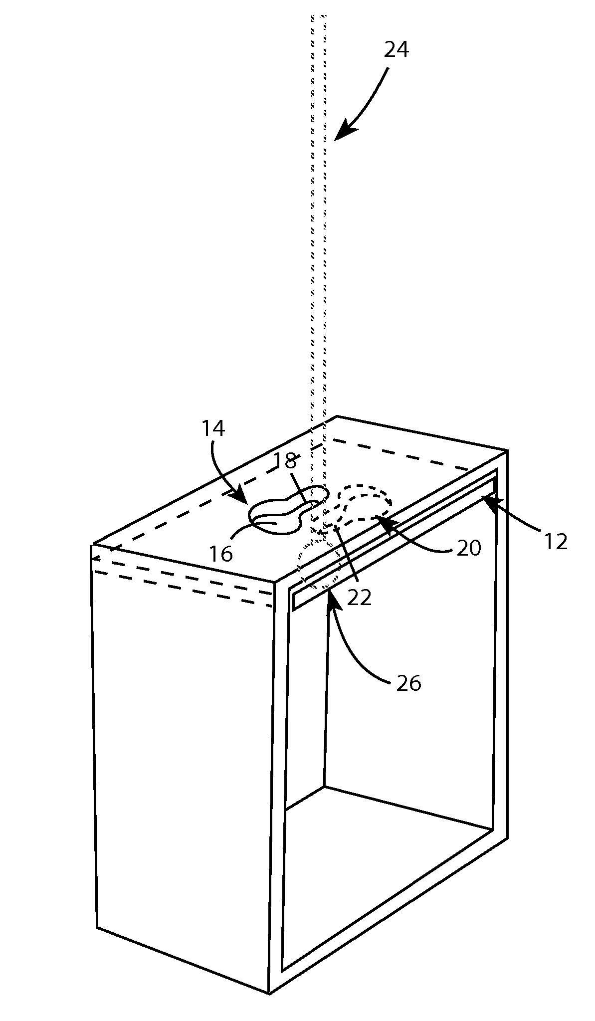
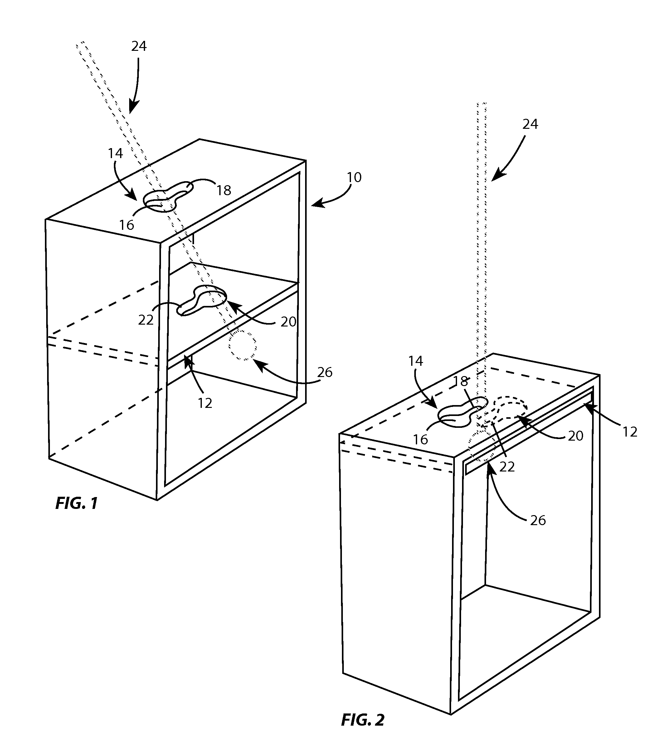
[0021]For the cable locking system description, a cable-like strap or other flexible or rigid member will be referred to as a cable. As shown in FIG. 1, components of the cable locking system consist of a rectangular or square band of rigid material 10 with a top, bottom and two sides, and a flat plate of rigid material 12. It should be noted that band 10 may be substituted with any number of alternative structures and band 10 is merely representative of one embodiment of various structures that can be used to create the cable locking system, in this case, a suspension bridge, scaffold or other hoisting device. It should also be noted that the flat plate of rigid material 12 may be substituted with any number of alternative structures and the flat plate of rigid material 12 is merely representative of one embodiment of various structures that can be used to create the cable locking system, in this case, a suspension bridge, scaffold or other hoisting device.

[0022]The flat plate is f...


PUM


Abstract

The cable locking system is a two-part device that locks a cable-like strap or other flexible or rigid member with an enlarged end into place by using an opposing arrangement of keyhole-shaped apertures bored into two rigid parts.The cable locking system requires no extra hardware to secure the connection, and can be retrofitted to fit virtually any size support system in numerous applications.The cable locking system can be installed quickly and easily without a need for tools, extra labor, or supporting equipment. In the case of a suspension bridge, the suspension parts can be pre-manufactured and assembled, then quickly and easily connected to complete the structure.The cable locking system makes the construction of a suspension bridge or other hoisting device as well as many kinds of structures simple and straightforward, with fewer parts that can potentially fail. The cable locking system can also easily be disassembled.

Description

CROSS-REFERENCE TO RELATED APPLICATIONS [0001]Not ApplicableFEDERALLY SPONSORED RESEARCH [0002]Not ApplicableSEQUENCE LISTING OR PROGRAM [0003]Not ApplicableBACKGROUND OF THE INVENTION[0004]This invention relates to a locking system that easily secures a cable-like strap or other flexible or rigid member with an enlarged end to a supporting structure by using an opposing arrangement of keyhole-shaped apertures. It is a simple, straightforward method that does not require bolting or other hardware-fastening methods to secure a connection. For the cable locking system background, a cable-like strap or flexible or rigid member will be referred to as a cable.[0005]In current methods to secure cables to a structure, a cable end crimp-type fastener or other enlarged end is installed at the end of a cable after threading the cable through a hole in the supporting structure. Cable is also attached to hardware that is installed in a supporting structure. For instance, eye-bolts are driven in...

Claims


Application Information

Patent Timeline
Patent Type & Authority Applications(United States)
IPC IPC(8): F16L3/00F16B1/00
CPCF16B21/09Y10T403/7015Y10T24/39Y10T24/3913Y10T24/45754Y10T24/3984
Inventor DENMARK, MARVIN A.
Owner DENMARK MARVIN ALBERT
Learn More