Collaborative Robot Manifold Tracker

a robot and manifold technology, applied in the direction of liquid/fluent solid measurement, fluid speed measurement, instruments, etc., can solve the problem that the sensor will tend to escape from the monitoring region of interes

a robot and manifold technology, applied in the direction of liquid/fluent solid measurement, fluid speed measurement, instruments, etc., can solve the problem that the sensor will tend to escape from the monitoring region of interes

US20130283926A1Active Publication Date: 2013-10-31UNITED STATES OF AMERICA

Image

  • Collaborative Robot Manifold Tracker
  • Collaborative Robot Manifold Tracker
  • Collaborative Robot Manifold Tracker

Examples


Embodiment Construction

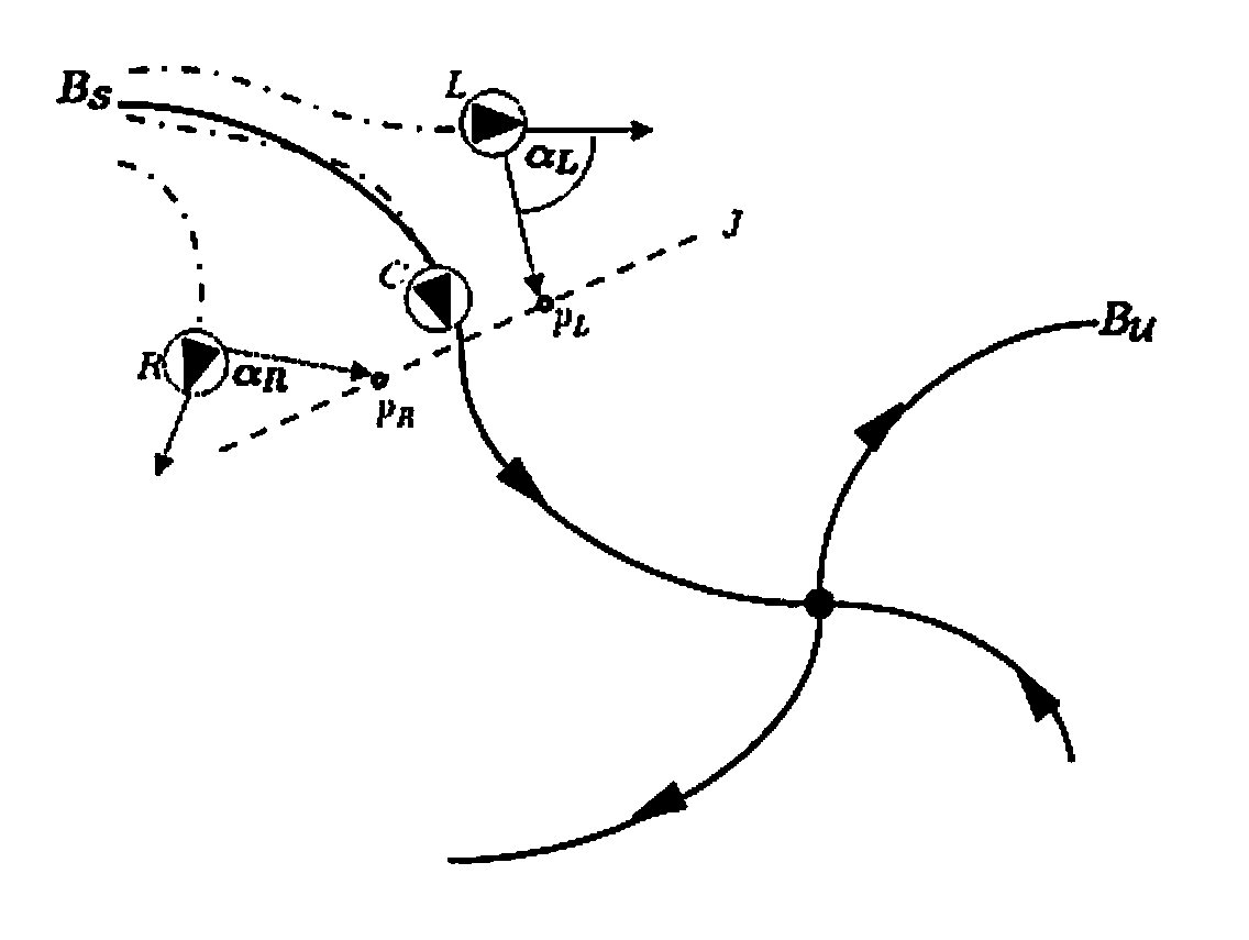
[0013]We consider the problem of controlling a team of N planar autonomous underwater vehicles (“AUVs”) or mobile autonomous underwater flow sensors, e.g. where each underwater flow sensor is tethered to a mobile autonomous watersurface craft, to collaboratively track the material lines that separate regions of flow with distinct fluid dynamics. This is similar to the problem of tracking the stable (and unstable) manifolds of a general nonlinear dynamical system where the manifolds separate regions in phase space with distinct dynamical behaviors. We assume the following 2D kinematic model for each of the AUVs:

dxi / dt=Vi cos θi+ui,  (1a)

dyi / dt=Vi sin θi+vi;  (1b)

where xi=[xi,yi]T is the vehicle's planar position, Vi and θi are the vehicle's linear speed and heading, and ui=[ui,vi]T is the velocity of the fluid current experienced / measured by the ith vehicle. Additionally, we assume each agent can be circumscribed by a circle of radius r, i.e., each vehicle can be equivalently describ...


PUM


Abstract

A collaborative control method for tracking Lagrangian coherent structures (LCSs) and manifolds on flows employs at least three autonomous sensors each equipped with a local flow sensor for sensing flow in a designated fluid medium, e.g. water or air. A first flow sensor is a tracking sensor while the other sensors are herding sensors for controlling and determining the actions of the tracking sensor. The tracking sensor is positioned with respect to the herding sensors in the fluid medium such that the herding sensors maintain a straddle formation across a boundary; obtaining a local fluid flow velocity measurement from each sensor. A global fluid flow structure is predicted based on the local flow velocity measurements. In a water medium, mobile autonomous underwater flow sensors may be deployed with each tethered to a watersurface craft.

Description

CROSS-REFERENCE TO RELATED APPLICATIONS[0001]This application claims the benefit of U.S. Provisional Application 61 / 638,694 filed on Apr. 26, 2012, and incorporated herein by reference.FIELD OF THE INVENTION[0002]The invention is directed to tracking coherent structures and manifolds on flows in a designated fluid medium, and in particular to deploying mobile autonomous underwater flow sensors, e.g. each tethered to a watersurface craft, to track stable / unstable manifolds of general 2D conservative flows through local sensing alone.BACKGROUND OF THE INVENTION[0003]In realistic ocean flows, time-dependent coherent structures, or Lagrangian coherent structures (LCS), are similar to separatrices that divide the flow into dynamically distinct regions. LCS are extensions of stable and unstable manifolds to general time-dependent flows (see, e.g., G. Haller and G. Yuan, “Lagrangian coherent structures and mixing in two-dimensional turbulence,” Phys. D, vol. 147, pp. 352-370 (December 2000...

Claims


Application Information

Patent Timeline
31 Oct 2013
Publication
US20130283926A1
IPC
G01F1/00
CPC
G01F1/00; G01P5/00; G06F17/00
Inventors
SCHWARTZ, IRA B.; HSIEH, MONG-YING ANI