
System and method for cooling and extraction of heavy ashes with increase in total boiler efficiency

Inactive Publication Date: 2013-10-31
MAGALDI POWER SPA
View PDF5 Cites 2 Cited by
  • Summary
  • Abstract
  • Description
  • Claims
  • Application Information

AI Technical Summary

Benefits of technology

The invention is a cooling system for ash in a boiler. The system uses a partitioned structure to direct cooling air through holes and cracks in the ash, resulting in a more efficient heat exchange than traditional systems. This results in higher cooling efficiency and a reduction of cooling air needed, making it more compact and simple. The system also prevents excessive temperatures and the need for a separate wet cooling system. Overall, the invention improves combustion efficiency and reduces losses.

Problems solved by technology

In fact, the efficiency of ash cooling is limited to the exposed and available surface for the heat exchange with the air.
In fact, if it is alter over such limit, the stechiometric ratio between fuel and air results in a reduction of combustion efficiency and in an increase of losses to the fireplace.
The combustion of these latter in high power boilers leads to a significant production of heavy ash, even up to 100 tons / hour, often containing high percentages of unburned.

Method used


Image

  • System and method for cooling and extraction of heavy ashes with increase in total boiler efficiency
  • System and method for cooling and extraction of heavy ashes with increase in total boiler efficiency
  • System and method for cooling and extraction of heavy ashes with increase in total boiler efficiency

Examples


first embodiment

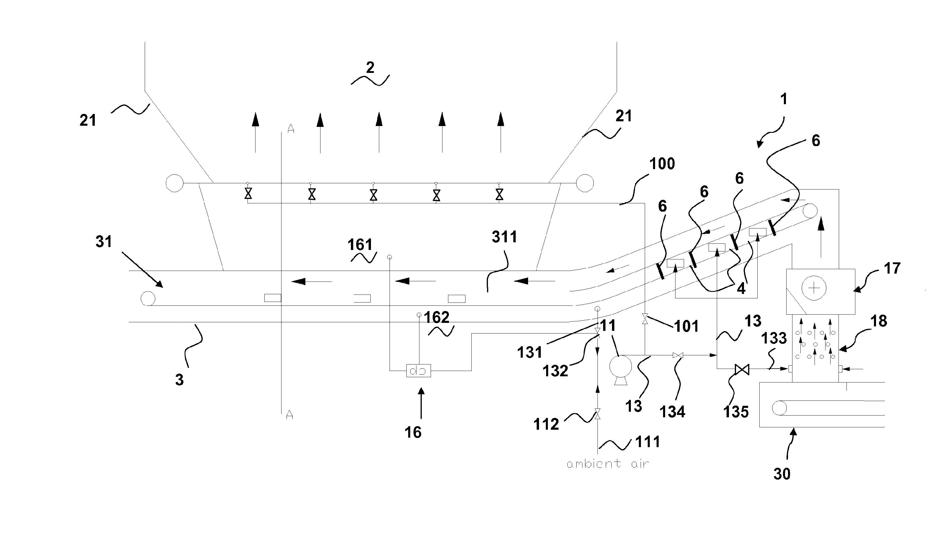
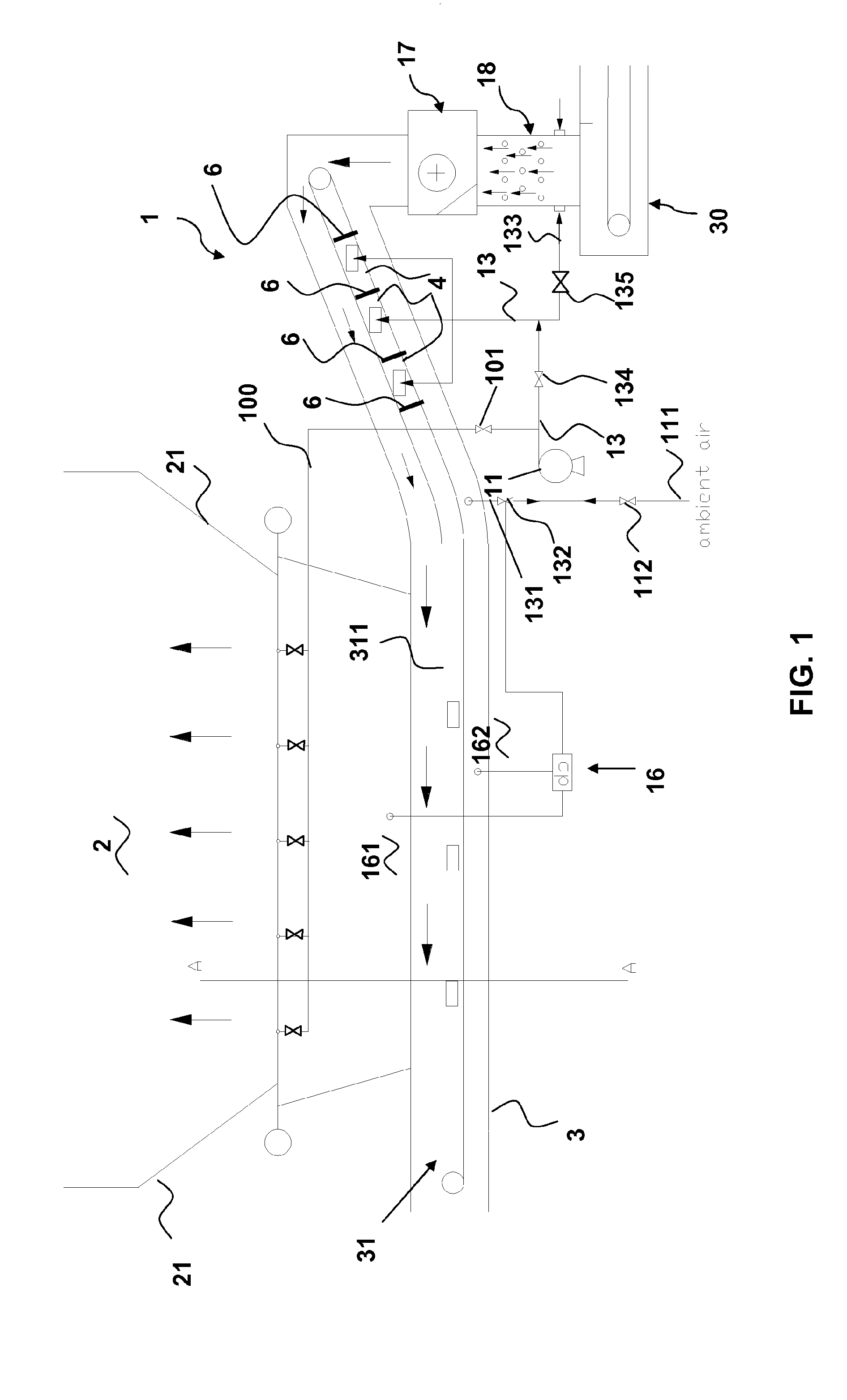
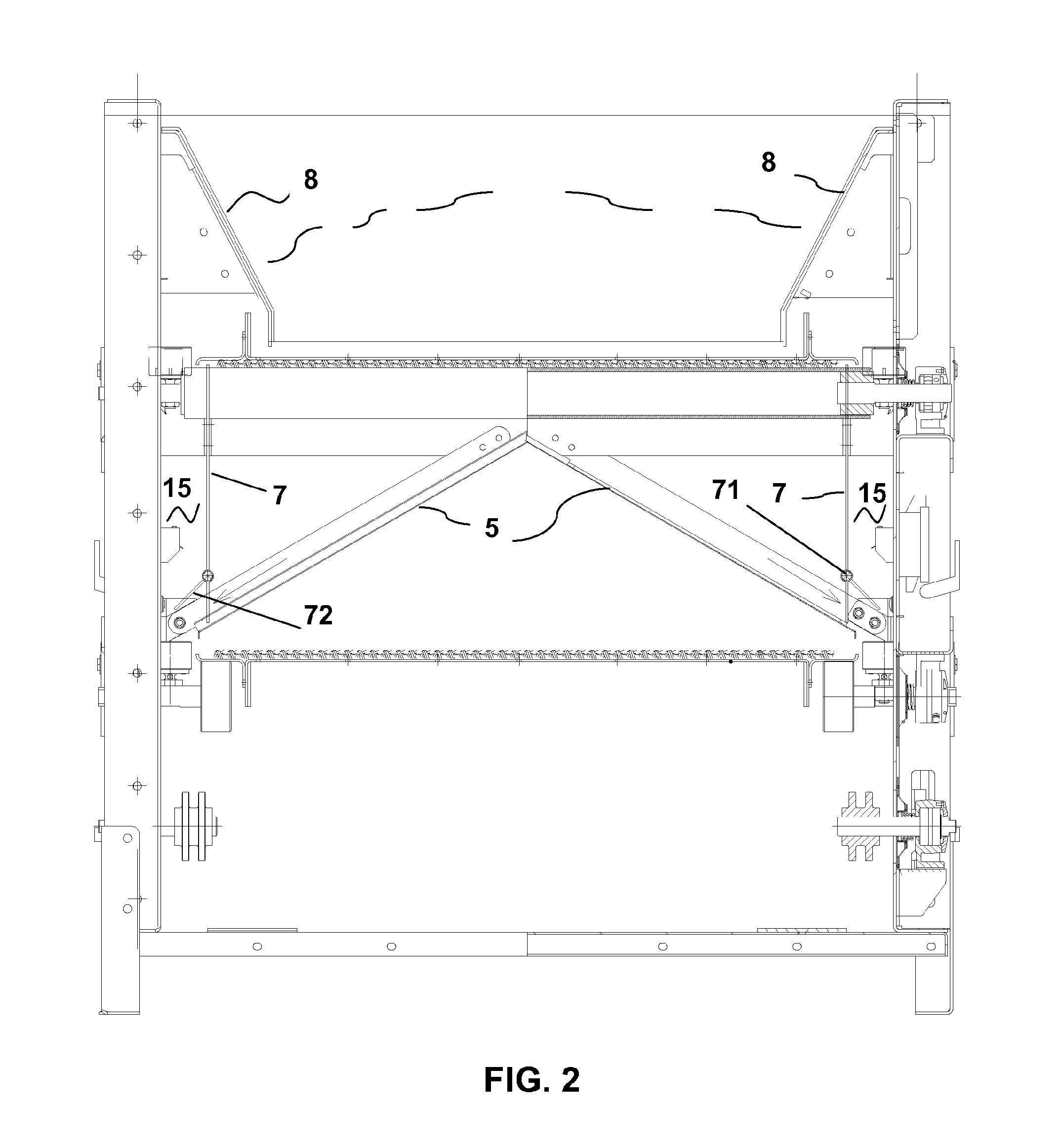
[0052]In a first embodiment shown in FIGS. 2 and 2A, the partitioned region 4 is affected by transverse baffles 6, arranged transversely to the transport surface 311 with respect to the direction of this advancement, and bounded laterally by two longitudinal baffles 7, spanning according said progress direction.

[0053]The lateral baffles 7 are arranged near the transport surface 311 and its roller support 14, so as not to interfere with the movement of each body but at the same time minimizing light outflows through the air cooling alleged in the partitioned region 4.

[0054]In addition, the arrangement of the transverse baffles 6 of the partitioning of the region below the transport surface 311 ensures a labyrinth seal to the cooling air, assisting the sealing action to the lateral air outflows by means of baffles 7.

[0055]Always in this example, the partitioned region 4 is bounded below by a tilted-surface plate 5 for recovering of any lost fines during the transport on the surface 31...

second embodiment

[0056]In the partitioned region 4 shown in FIGS. 3, 3A, transverse baffles 6 are still provided, in this case associated with bulkheads or lateral baffles 51 which extend longitudinally along the belt 31, substantially parallel to it, upper to the transport surface 311 and each along a respective side of this, where the contact or proximity of said baffles 51 with the containment ends 81 of the transport belt 31, allows limiting the passage of air that does not pass through the hole belt 31.

[0057]In this second embodiment, each of the tilted-surface plate 5 presents a lower end door 725 selectively openable to the outside through a mechanism 715, preferably hinged, for the purposes of downflow of fines toward the bottom of said containment casing 3. Thus, when—during normal operation—the door 725 is closed, it keeps a tight air, being in direct contact with the side wall of the casing 3.

[0058]A further embodiment may provide the combined presence of these side walls arranged at the ...


PUM


Abstract

A cooling system for heavy ashes of the type adapted to be used in association with a combustion chamber, in particular for large flow rates of heavy ashes deriving, for example from solid fossil fuel, in an energy-production unit is described. The cooling system has: a transport belt for transporting the heavy ashes, adapted to be arranged below the combustion chamber and having a containment casing and a transport surface equipped with openings for the transit of cooling air, and cooling means for cooling the heavy ashes received on the transport surface.

Description

FIELD OF THE INVENTION[0001]The present invention relates to a cooling system for heavy ashes of the type apt to be used in association with a combustion chamber, in particular for large flow rates of ashes deriving for example from solid fossil fuel in an energy-production unit.BACKGROUND OF THE INVENTION[0002]Well-known dry cooling and extraction systems for heavy ashes produced in combustion chambers (or boilers) from solid fuel are based upon air cooling of an ash bed. To this end, the latter is transported on a belt resistant to high temperatures placed just below the throat of the boiler. Cooling air is drawn into the extraction system by the negative pressure present within the boiler, passing through proper openings of a containment casing of the belt. The air then runs the system and the ash bed in countercurrent to the sense of direction, thus operating the cooling of ashes and equipments.[0003]A system for extraction and cooling of that type just described is disclosed in...

Claims


Application Information

Patent Timeline
IPC IPC(8): F23J1/02
CPCF23J1/02F23J2900/01002F23J2900/01003F23J2900/01007F23J2900/01009F23H15/00F24B13/02
Inventor MAGALDI, MARIOCARREA, ALBERTOSORRENTI, ROCCO
Owner MAGALDI POWER SPA
Learn More