
Heat exchanger with thermal storage function and method of manufacturing the same

a technology of heat exchanger and function, which is applied in the direction of regenerative heat exchangers, indirect heat exchangers, lighting and heating apparatus, etc., can solve the problem of sharp drop in the cooling capacity of air conditioners, and achieve the effect of greater collapse and greater collapse degr

Active Publication Date: 2013-10-31
MAHLE INT GMBH
View PDF17 Cites 24 Cited by
  • Summary
  • Abstract
  • Description
  • Claims
  • Application Information

AI Technical Summary

Benefits of technology

The patent text describes a method for manufacturing cool storage material containers for heat exchangers. The method involves using aluminum plates and a heat exchange tube system to create a container that can contain cool storage material. The aluminum plates are pressed and formed into the shape of the container, with bulge portions and a rim portion. A cool storage material charging member is also prepared to insert into the container. The components of the heat exchanger, such as the header tanks, heat exchange tubes, outer fins, and side plates, are assembled together and fixed, then the aluminum plates are brazed together. The resulting assembly prevents leakage of the cool storage material and ensures the manufacturing of reliable heat exchangers with a thermal storage function.

Problems solved by technology

However, an ordinary car air conditioner has a problem in that, when the engine of an automobile in which the air conditioner is mounted is stopped, a compressor driven by the engine stops, and supply of refrigerant (medium for conveying cool) to an evaporator stops, whereby the cooling capacity of the air conditioner sharply drops.

Method used


Image

  • Heat exchanger with thermal storage function and method of manufacturing the same
  • Heat exchanger with thermal storage function and method of manufacturing the same
  • Heat exchanger with thermal storage function and method of manufacturing the same

Examples


Embodiment Construction

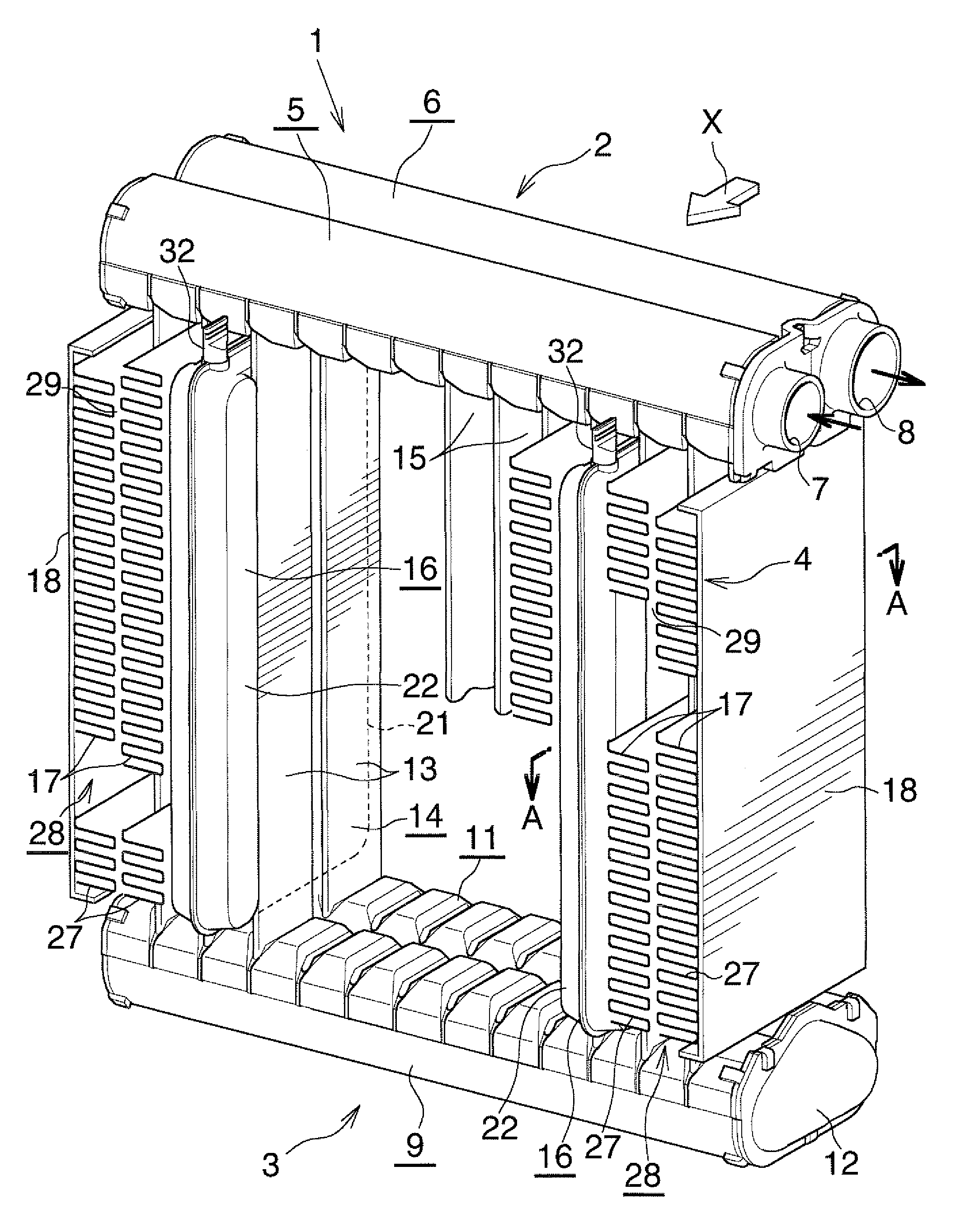
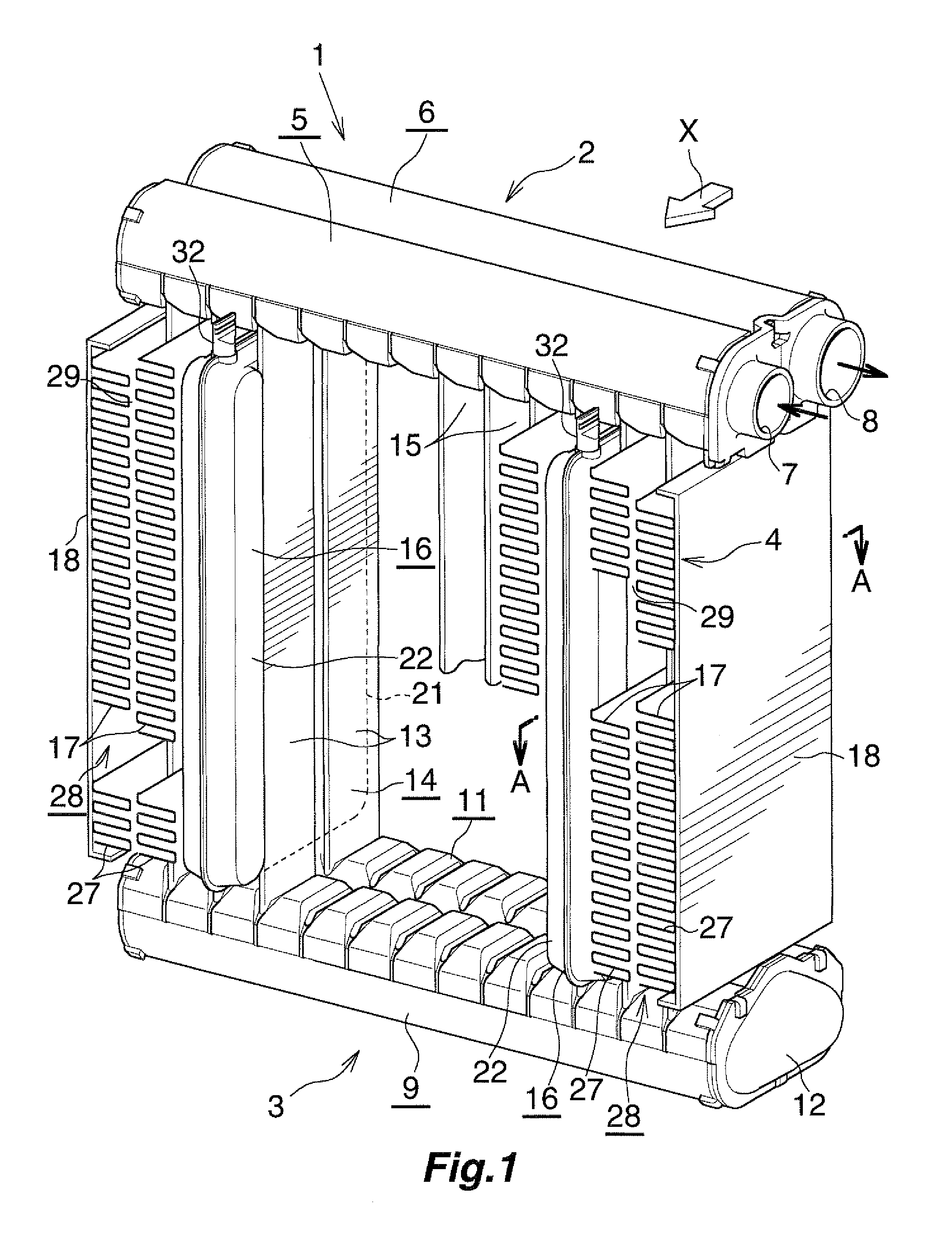
[0030]The embodiments will now be described with reference to the accompanying drawings, wherein like reference numerals designate corresponding or identical elements throughout the various drawings.

[0031]In this embodiment, a heat exchanger with a thermal storage function according to the embodiment is applied to an evaporator with a cool storage function (a function of storing cool).

[0032]Throughout the drawings, like portions and like members are denoted by the same reference numerals, and their descriptions will not be repeated.

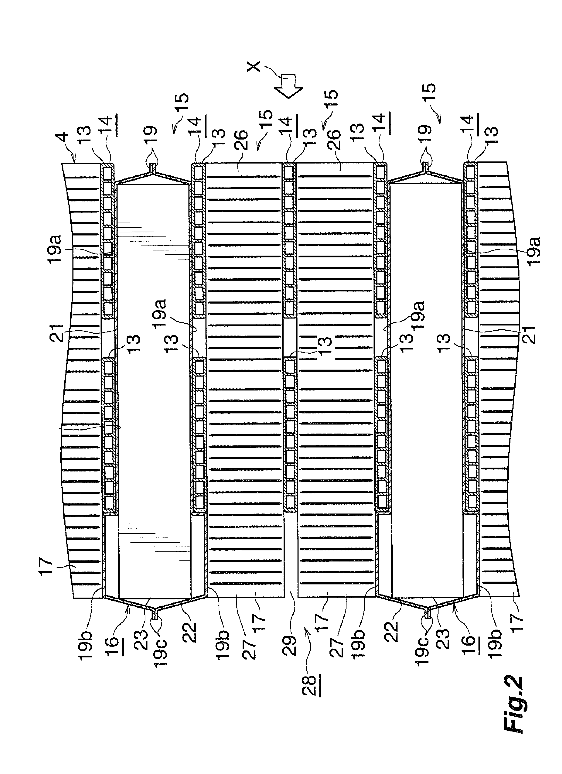
[0033]In the following description, the downstream side with respect to an air-passing direction (a direction represented by arrow X in FIGS. 1 and 2) will be referred to as the “front,” and the opposite side as the “rear.” Also, the left-hand and right-hand sides of FIG. 1 will be referred to as “left” and “right,” respectively.

[0034]Furthermore, the term “aluminum” as used in the following description encompasses aluminum alloys in addition to pure alum...


PUM

PropertyMeasurementUnit
Thicknessaaaaaaaaaa
Shapeaaaaaaaaaa
Radiusaaaaaaaaaa

Abstract

A heat exchanger with a thermal storage function includes a plurality of heat exchange tubes, a plurality of thermal storage material containers, and a first thermal storage material charging member. A circumferential wall of the first thermal storage material charging member is deformed such that a collapsed portion is formed on the first thermal storage material charging member and the thermal storage material charging passage is closed and sealed. The collapsed portion of the first thermal storage material charging member includes a first collapsed part and a second collapsed part. A relation T2<T1≦2t is satisfied where “t” represents a thickness of the circumferential wall of an uncollapsed portion of the first thermal storage material charging member, “T1” represents a thickness of the first collapsed part, and “T2” represents a thickness of the second collapsed part.

Description

CROSS-REFERENCE TO RELATED APPLICATIONS[0001]The present application claims priority under 35 U.S.C. §119 to Japanese Patent Application No. 2012-102851, filed Apr. 27, 2012. The contents of this application are incorporated herein by reference in their entirety.BACKGROUND OF THE INVENTION[0002]1. Field of the Invention[0003]The present invention relates to a heat exchanger with a thermal storage function and a method of manufacturing the heat exchanger.[0004]2. Discussion of the Background[0005]For example, in order to protect the environment and improve fuel consumption of automobiles, there has been proposed an automobile designed to automatically stop the engine when the automobile stops, for example, so as to wait for a traffic light to change.[0006]However, an ordinary car air conditioner has a problem in that, when the engine of an automobile in which the air conditioner is mounted is stopped, a compressor driven by the engine stops, and supply of refrigerant (medium for conv...

Claims


Application Information

Patent Timeline
IPC IPC(8): F28D20/00
CPCF28D20/00F28D1/05391F28D20/02F28D2020/0008F28D2020/0069F28D2021/0085F28F9/0246F28F2220/00Y02E60/14Y10T29/4935B23P15/26
Inventor KAMOSHIDA, OSAMUNOBUSUE, MITSURU
Owner MAHLE INT GMBH
Learn More