Electronic component mounting device and image reading method used by electronic component mounting device

Active Publication Date: 2013-10-31
PANASONIC INTELLECTUAL PROPERTY MANAGEMENT CO LTD
View PDF12 Cites 7 Cited by
  • Summary
  • Abstract
  • Description
  • Claims
  • Application Information

AI Technical Summary

Benefits of technology

[0011]According to the present invention, in order to read the image of the electronic component by the line sensor arranged obliquely with respect to the substrate transfer direction by a given arrangement angle in a component extracting step of extracting the electronic component from the component supply unit by the mounting head, in the image acquiring step of selecting any one of the first-directional scanning operation and the second-directional scanning operation is to be conducted by the mounting head based on a predetermined scanning operation selecting condition in advance, and conducting the selected sca

Problems solved by technology

However, even when any one of the above-mentioned arrangements is applied as the arrangement of the line sensor, such an arrangement has advantages and disadvantages from the viewpoint of optimizing the efficiency of the component mounting operation by the mounting head.
However, when two mounting heads that face each other through the substrate are provided as a component mounting mechanism, because interference is generated between the respective mounting heads depending on the operating

Method used


Image

  • Electronic component mounting device and image reading method used by electronic component mounting device
  • Electronic component mounting device and image reading method used by electronic component mounting device
  • Electronic component mounting device and image reading method used by electronic component mounting device

Examples


Example

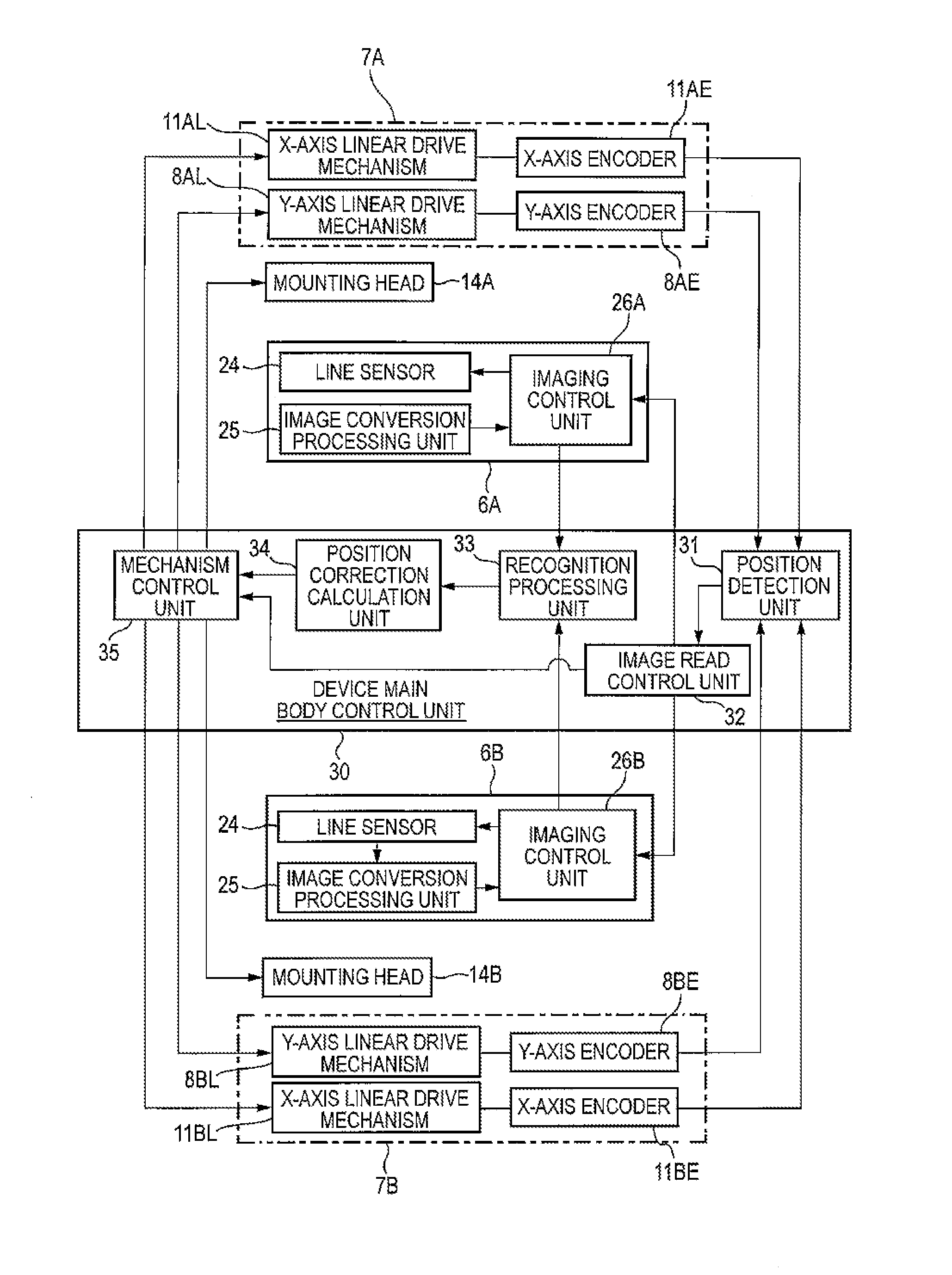
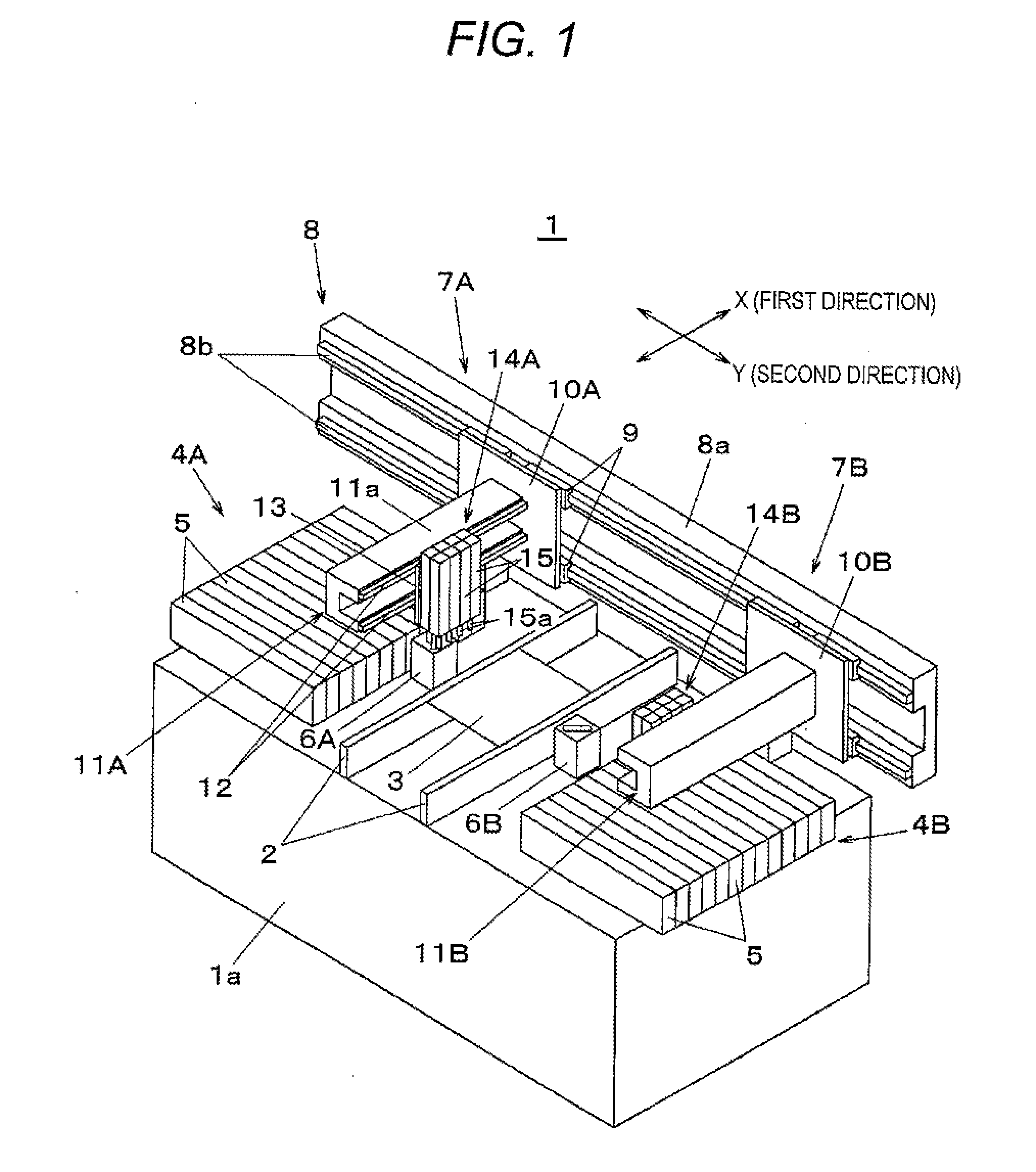
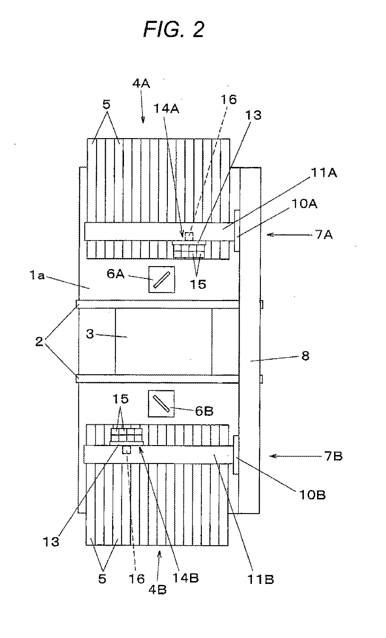
[0020]Subsequently, a description will be given of embodiments of the present invention with reference to the drawings. First, a structure of an electronic component mounting device 1 will be described with reference to FIGS. 1 and 2. The electronic component mounting device 1 is used in an electronic component mounting line for manufacturing a mounting board, and a plurality of the electronic component mounting devices 1 having the same structure is coupled with each other to configure the electronic component mounting line. Referring to FIG. 1, a substrate transfer mechanism 2 is arranged in the center of a base 1a in an X-direction. The substrate transfer mechanism 2 transfers a substrate 3 on which an electronic component is to be mounted in the X-direction (first direction). A substrate positioning unit that positions and holds the substrate at a mounting position is disposed in the transfer path for the substrate transfer mechanism 2, and the electronic component is mounted on...


PUM


Abstract

Image readers 6A and 6B that read images of electronic components held by first mounting heads 14A and 14B are each configured to have a line sensor arranged at an oblique arrangement angle with respect to a first direction, and in an image acquiring step of selecting any one of a first-directional scanning operation and a second-directional scanning operation is to be conducted by mounting heads 14A and 14B based on a predetermined scanning operation selecting condition set in advance, and acquiring image signals from the image readers 6A and 6B, image conversion processing of arranging one-dimensional images obtained by converting one-dimensional images sequentially output from the line sensor by an arrangement angle in parallel to generate a two-dimensional image is executed.

Description

DESCRIPTION[0001]1. Technical Field[0002]The present invention relates to an electronic component mounting device that mounts electronic components on a substrate, and an image reading method that reads an image of the electronic components in the electronic component mounting device.[0003]2. Background Art[0004]In the electronic component mounting device that mounts the electronic components such as a semiconductor chip on the substrate, a camera using a line sensor such as a CCD in which image pickup elements are aligned in rows has been widely used up to now as an image reader for correcting a position gap between the electronic components and the substrate at the time of mounting by image recognition. When the image is read by the line sensor, there is a need to conduct scanning operation of relatively moving an electronic component to be read, and the line sensor in a direction orthogonal to an element array direction. For that reason, in the arrangement of the line sensor in t...

Claims


Application Information

Patent Timeline
IPC IPC(8): H05K13/04
CPCH05K13/0404H05K13/0812
Inventor OKADA, YASUICHIARASE, MASAYUKI
Owner PANASONIC INTELLECTUAL PROPERTY MANAGEMENT CO LTD
Why Eureka
Try Eureka