Network switch

Active Publication Date: 2013-10-17
APRESIA SYST LTD
View PDF3 Cites 5 Cited by
  • Summary
  • Abstract
  • Description
  • Claims
  • Application Information

AI Technical Summary

Benefits of technology

[0034]According to the present invention, the time required for the switching-over to the ba

Problems solved by technology

If a failure occurs in any port of the network switch, the unicast frame to be transferred to the port having caused the failure is not normally relayed and communication is interrupted.
In the related-art network switch, however, if a failure occurs in a port for which the LAG is set, a problem arises in that about several hundreds mill

Method used


Image

  • Network switch
  • Network switch
  • Network switch

Examples


Example

[0040]An embodiment of the present invention will be described below with reference to the accompanying drawings.

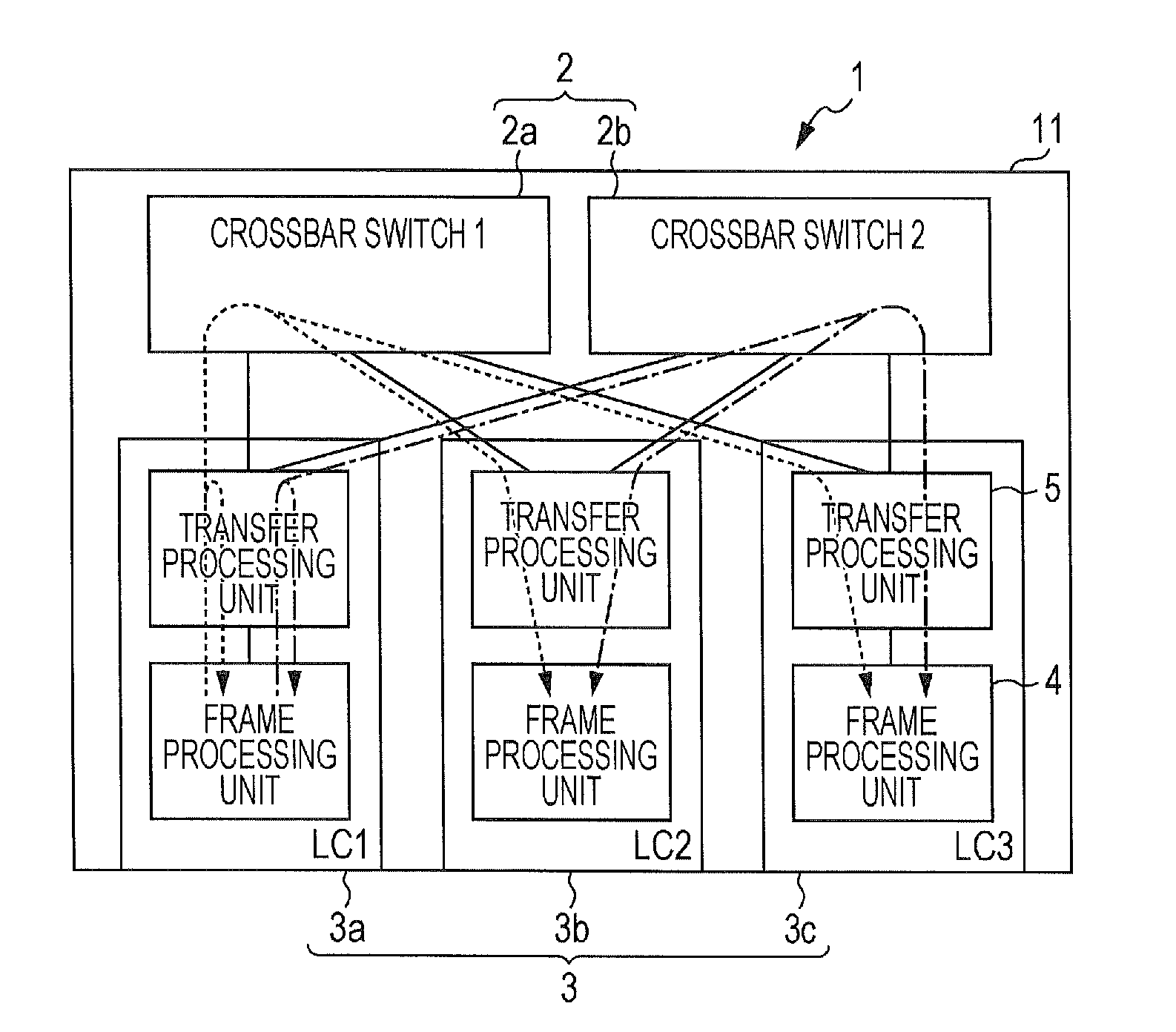
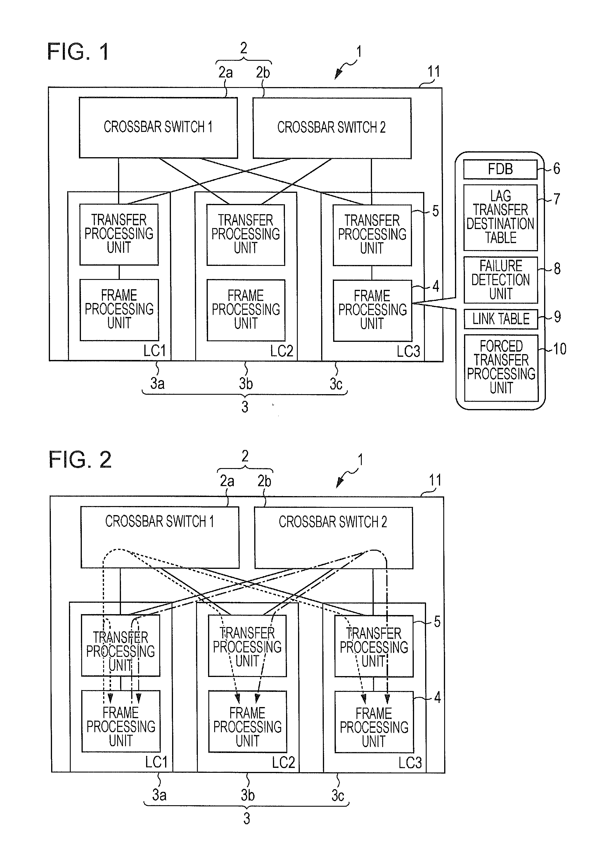
[0041]FIG. 1 is a block diagram of a network switch according to the embodiment. The embodiment is described, by way of example, in connection with the case where a network switch 1 is a chassis type switch.

[0042]As illustrated in FIG. 1, the network switch 1 includes a plurality of line cards 3 within a chassis 11. While FIG. 1 illustrates the case including three line cards 3a to 3c (LC1, LC2 and LC3), the number of line cards 3 is not limited to three. The network switch 1 is applied to, for example, a ring network.

[0043]The line cards 3 are interconnected within the device (i.e., the network switch) via a crossbar switch 2 serving as a relay route. While FIG. 1 illustrates the case where each line card 3 includes two crossbar switches 2a and 2b (denoted respectively by a crossbar switch 1 and a crossbar switch 2 in FIG. 1) for redundancy of the relay route, the number...


PUM


Abstract

A network switch is provided which can shorten a time required for switching-over to a backup route when a failure has occurred in a port for which an LAG is set. The network switch includes a failure detection unit for detecting a port failure, and a forced transfer processing unit for, when a failure is detected in a port at a transfer destination as a target in trying to transfer a received unicast frame and when an link aggregation group is set for a plurality of ports including the relevant port at the transfer destination, forcibly transferring the received unicast frame to another port for which the same link aggregation group as that set for the relevant port at the transfer destination is set.

Description

[0001]The present application is based on Japanese patent application No. 2012-93104 filed on Apr. 16, 2012, the entire contents of which are incorporated herein by reference.BACKGROUND OF THE INVENTION[0002]1. Field of the Invention[0003]The present invention relates to a network switch.[0004]2. Description of the Related Art[0005]A chassis type switch and a box type switch are known as examples of a network switch. The chassis type switch includes a plurality of line cards within a chassis (casing).[0006]There is a network switch of the type including an FDB (Forwarding Database) and executing frame transfer in accordance with the FDB. The term “FDB” implies a database for defining correspondence between a destination MAC (Media Access Control) address and an output port (i.e., an identifier of a line card and an identifier of the output port at a transfer destination in the case of the chassis type switch, or only an identifier of the output port in the case of the box type switc...

Claims


Application Information

Patent Timeline
IPC IPC(8): H04J3/14H04L47/41H04L45/24H04L45/247
CPCH04L41/0654H04L49/557H04L49/1576
Inventor AOSHIMA, KENJISAWAGUCHI, CHIKARA
Owner APRESIA SYST LTD
Why Eureka
Try Eureka