Unlock instant, AI-driven research and patent intelligence for your innovation.

Wireless relay device, wireless LAN system, wireless relay method and program

a wireless relay and wireless lan technology, applied in the direction of sustainable communication technology, climate sustainability, high-level techniques, etc., can solve the problems of waste of electric power, disadvantageous invitation of data congestion, and inability to point out superfluous power consumption due to non-operational aps, so as to improve power saving capability, reduce the number of times of beacon emission, and avoid connection delay

Inactive Publication Date: 2013-10-31
NEC CORP
View PDF7 Cites 3 Cited by
  • Summary
  • Abstract
  • Description
  • Claims
  • Application Information

AI Technical Summary

Benefits of technology

The present invention reduces power consumption by decreasing the number of times beacons are emitted. This is achieved without causing a connection delay, which means that power saving can be achieved without causing delays.

Problems solved by technology

However, since the band (the upper-limit data amount that can be simultaneously transmitted) of the APs is restricted, if many STAs are connected to a specific AP, data congestion is disadvantageously invited.
Meanwhile, in the wireless LAN system including many APS, in addition to the disadvantage (data congestion) described above, superfluous power consumption due to non-operating APs can be pointed out.
In the situation such as non-business hours in which only a small number of STAs or no STA is present, it is a waste of electric power to keep all APs in operation.
This problem of power consumption cannot be ignored particularly in the case of a wireless LAN system having a large number of APs.

Method used


Image

  • Wireless relay device, wireless LAN system, wireless relay method and program
  • Wireless relay device, wireless LAN system, wireless relay method and program
  • Wireless relay device, wireless LAN system, wireless relay method and program

Examples


Embodiment Construction

[0029]Embodiments of the present invention are described below with reference to the drawings. Note that it is obvious that various detailed specific or actual examples and examples of numerical values, character strings, and other signs in the description below are merely for reference and the idea of the present invention is not restricted by all or part of these examples. Also, known schemes, known procedures, known architectures, known circuit structures, and others (hereinafter, “known matters”) are not described in detail for the purpose of simplifying the description, and this is not meant to intentionally exclude all or part of these known matters. Since these known matters can be known by persons skilled in the art at the time of filing an application of the present invention, they are naturally included in the description below.

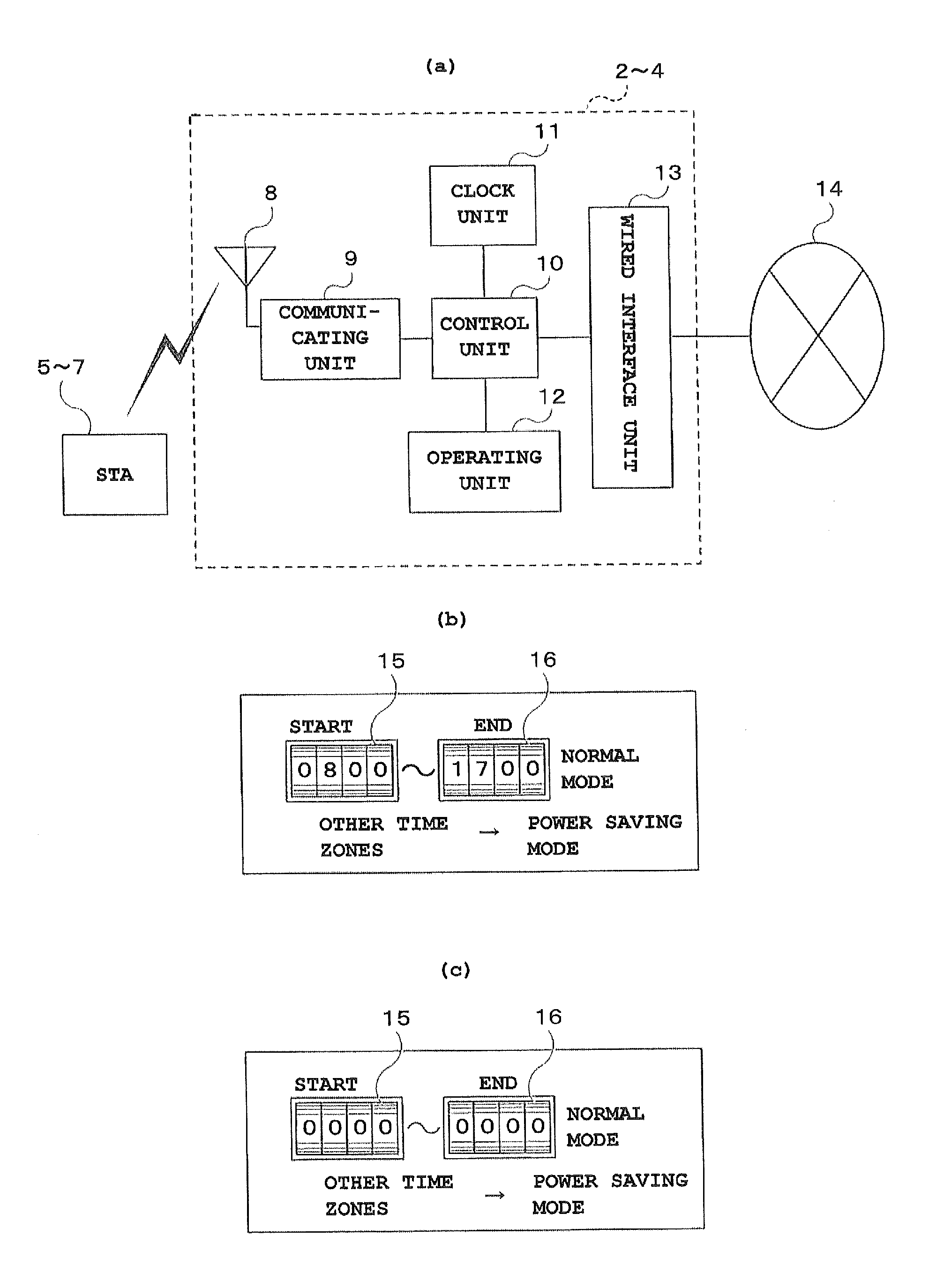
[0030]FIG. 1 is a schematic entire structural diagram of a wireless LAN system. In this drawing, a floor 1 is provided with a plurality of wireless...


PUM


Abstract

A wireless relay device emits a beacon and makes a wireless connection with a terminal responding to the beacon, which includes a selecting section capable of alternatively selecting a normal mode in which the beacon is emitted in a first cycle and a power saving mode in which the beacon is emitted in a second cycle longer than the first cycle.

Description

TECHNICAL FIELD[0001]The present invention relates to a wireless relay device, wireless LAN system, wireless relay method, and program and, in detail, to a wireless relay device, wireless LAN system, wireless relay method, and program with improved power saving capability.BACKGROUND ART[0002]A wireless LAN system is a useful system allowing a wireless access to a network resource such as a wired LAN and the Internet via a wireless relay device called an access point (hereinafter abbreviated as an AP), and has been widely spread to homes, workplaces, and public facilities such as stations and airports.[0003]An electronic device capable of using a wireless LAN system is referred to as a wireless LAN terminal, simply a terminal, or a wireless LAN station (hereinafter abbreviated as an STA). Typical STAs include a personal computer and an information terminal. While these are generally portable or transportable (carriable), part of those of a fixed type may be used as STAs with an advan...

Claims


Application Information

Patent Timeline
Patent Type & Authority Applications(United States)
IPC IPC(8): H04W52/02
CPCH04W52/0203H04W52/0248Y02D30/70
Inventor SHINOKI, YUDAI
Owner NEC CORP