Computed tomography (CT) data acquisition

a computed tomography and data acquisition technology, applied in tomography, instruments, applications, etc., can solve the problems of increasing the overall cost of the scanner, affecting the image quality of the reconstructed image data, and affecting the overall quality of the scanner

Active Publication Date: 2013-10-31
KONINKLIJKE PHILIPS ELECTRONICS NV
View PDF2 Cites 8 Cited by
  • Summary
  • Abstract
  • Description
  • Claims
  • Application Information

AI Technical Summary

Problems solved by technology

However, if the integration period timing with respect to the angular position range is not accurate, then, in actuality, the projection data corresponds to a different angular position range, and this may result in degraded image quality of the reconstructed image data.
Unfortunately, there is a natural rotating gantry position error in which t

Method used


Image

  • Computed tomography (CT) data acquisition
  • Computed tomography (CT) data acquisition
  • Computed tomography (CT) data acquisition

Examples


Embodiment Construction

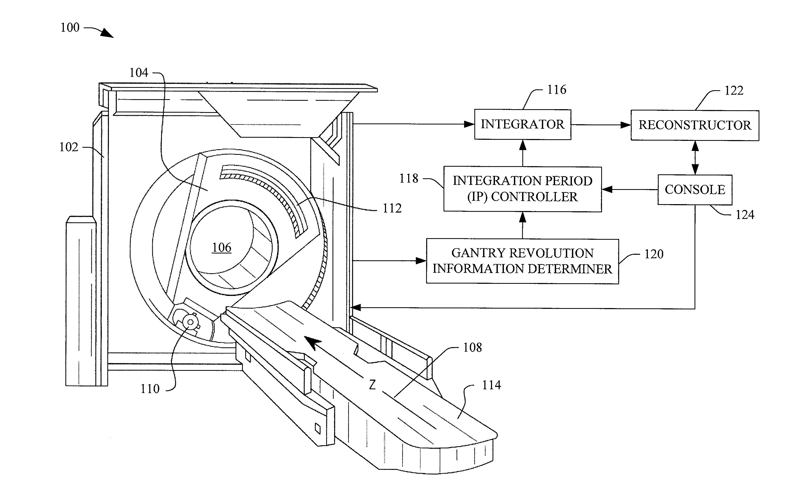
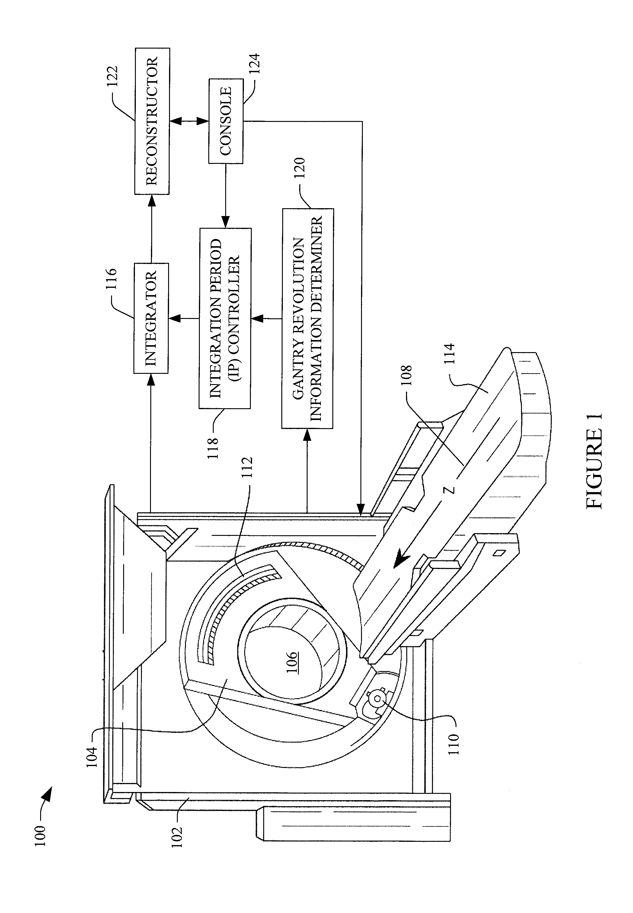
[0021]FIG. 1 schematically illustrates an imaging system such as a computed tomography (CT) scanner 100. The scanner 100 includes a stationary gantry 102 and a rotating gantry 104, which is rotatably supported by the stationary gantry 102. The rotating gantry 104 rotates around an examination region 106 about a longitudinal or z-axis 108 one or more times for one or more data acquisition cycles. A patient support 114, such as a couch, supports a patient in the examination region 106.

[0022]A radiation source 110, such as an x-ray tube, is supported by and rotates with the rotating gantry 104 around the examination region 106. The radiation source 110 emits radiation that is collimated by a source collimator to produce a generally fan, wedge, or cone shaped radiation beam that traverses the examination region 106. A radiation sensitive detector array 112 includes a one or two dimensional array of detector pixels that respectively detect radiation that traverses the examination region ...


PUM


Abstract

An imaging system (100) includes a stationary gantry (102), a rotating gantry (104), a radiation source (110), and a detector array (112). The detector array detects radiation for a plurality of integration periods during a rotating gantry revolution, the plurality of integration periods corresponds to different angular position ranges, and the detector array generates a signal indicative of the detected radiation respectively for the plurality of integration periods. The system further includes an integration period controller (118) that generates an integration period timing signal that includes timing for a start of each of the integration periods for a revolution of the rotating gantry based at least on a time duration of a previous revolution of the rotating gantry around the examination region, wherein the integration timing signal is used trigger the plurality of integration periods.

Description

FIELD OF THE INVENTION[0001]The following generally relates to imaging system data acquisition and is described with particular application to computed tomography (CT).BACKGROUND OF THE INVENTION[0002]A computed tomography (CT) scanner includes a rotating portion rotatably supported by a stationary portion. The rotating portion supports an x-ray tube, which emits radiation that traverses an examination region and a portion of an object or subject therein, and a detector array that detects radiation traversing the examination region and generates projection data indicative of the detected radiation. A reconstructor reconstructs the projection data and generates volumetric image data indicative of the portion of the object or subject in the examination region. One or more images can be generated based on the image data.[0003]The detector array includes detector pixels that convert detected x-ray photons into electrical signals indicative thereof. For each revolution of the rotating ga...

Claims


Application Information

Patent Timeline
IPC IPC(8): A61B6/00A61B6/03
CPCA61B6/5294A61B6/032A61B6/54A61B6/545A61B6/547
Inventor SHARPLESS, RONALD B.
Owner KONINKLIJKE PHILIPS ELECTRONICS NV
Why Eureka
Try Eureka