Stent-graft prosthesis for placement in the abdominal aorta

a technology of aortic stent and prosthesis, which is applied in the field of endoluminal medical devices and procedures, can solve the problems of inability to use stent-grafts to bypass internal arteries, insufficient blood flow lumen, and insufficient aneurysmal site, and achieves the effect of greater flexibility

Active Publication Date: 2013-10-31
MEDTRONIC VASCULAR INC
View PDF4 Cites 17 Cited by
  • Summary
  • Abstract
  • Description
  • Claims
  • Application Information

AI Technical Summary

Problems solved by technology

The use of stent-grafts to internally bypass, within the aorta or flow lumen, the aneurysmal site, is also not without challenges.
As a result, blood leakage is prone to occur into the space between the outer surface of the main aortic stent-graft and the surrounding aortic wall between the edge of the graft material surrounding the fenestrations and the adjacent vessel wall.
Similar blood leakage can result from post-implantation migration or movement of the stent-graft causing misalignment between the fenestration(s) and the branch artery(ies), which may also result in impaired flow into the branch artery(ies).
This connection between the branch vessel stent-graft and main vessel stent-graft may be difficult to create effectively in situ and is a site for potential leakage.
Similar issues arise in treating so-called short-neck infrarenal aneurysms, in which only a small length (i.e., less than 10 mm) of non-aneurysed tissue is present between the renal arteries and the proximal end of the infrarenal aneurysm.
Since juxtarenal and suprarenal aneurysms extend up to or above the renal arteries, there is an insufficient non-aneurysmal length or neck of the aorta distally of (i.e., distal to or downstream of) the renal arteries for a stent-graft to deploy and seal against the vessel wall.
Custom designed stent-grafts require a significant lead time, i.e., 6-8 weeks, and are costly to design and manufacture.

Method used


Image

  • Stent-graft prosthesis for placement in the abdominal aorta
  • Stent-graft prosthesis for placement in the abdominal aorta
  • Stent-graft prosthesis for placement in the abdominal aorta

Examples


Embodiment Construction

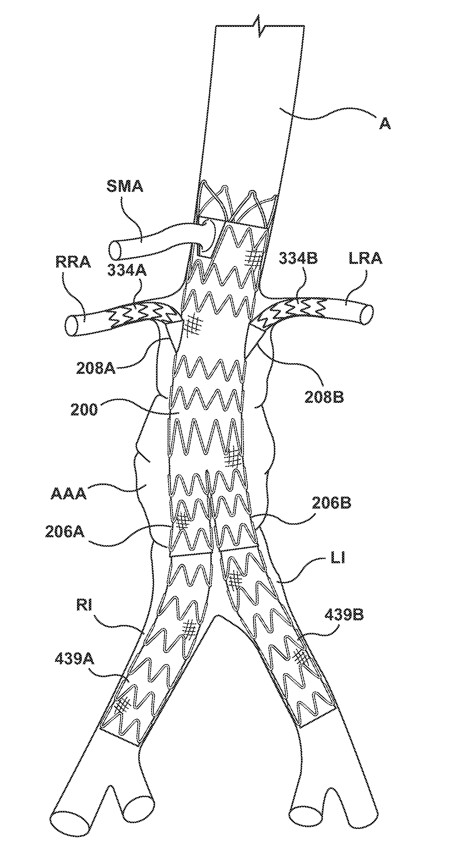
[0027]Specific embodiments of the present invention are now described with reference to the figures, wherein like reference numbers indicate identical or functionally similar elements. Unless otherwise indicated, the terms “distal” and “proximal” are used herein with reference to the direction of blood flow from the heart in using the stent-graft system in the vasculature: “distal” indicates an apparatus portion distant from, or a direction away from the heart and “proximal” indicates an apparatus portion near to, or a direction towards to the heart. In addition, the term “self-expanding” is used in the following description with reference to one or more stent structures of the prostheses hereof and is intended to convey that the structures are shaped or formed from a material that can be provided with a mechanical memory to return the structure from a compressed or constricted delivery configuration to an expanded deployed configuration. Non-exhaustive exemplary self-expanding mate...


PUM


Abstract

A self-expanding main vessel stent-graft includes a trunk portion configured for placement within the abdominal aorta and a bifurcated portion configured for placement above the aortic bifurcation of the common iliac arteries. The trunk portion includes a proximal end section having an anchor stent and a seal stent that accommodates a scallop or open-top fenestration; a suprarenal body section having at least one stent of variable stiffness to accommodate branch vessel prosthesis deployed alongside the main vessel stent-graft; a branch connection section having opposing couplings for connecting the main vessel stent-graft to branch vessel prostheses deployed within the renal arteries; an infrarenal body section having at least one stent of uniform stiffness; and a transition section for transitioning into the bifurcated portion. The main vessel stent-graft is configured to treat short-neck infrarenal, juxtarenal, and / or suprarenal aneurysms in a wide range of patient anatomies.

Description

FIELD OF THE INVENTION[0001]This invention relates generally to endoluminal medical devices and procedures, and more particularly to an endoluminal prosthesis or graft configured for placement in the abdominal aorta having branch vessels extending therefrom.BACKGROUND OF THE INVENTION[0002]Aneurysms and / or dissections may occur in blood vessels, and most typically occur in the aorta and peripheral arteries. Depending on the region of the aorta involved, the aneurysm may extend into areas having vessel bifurcations or segments of the aorta from which smaller “branch” arteries extend. Abdominal aortic aneurysms include aneurysms present in the aorta distal to the diaphragm, e.g., pararenal aorta and the branch arteries that emanate therefrom, including the renal arteries and the superior mesenteric artery (SMA). Abdominal aortic aneurysms are bulges or weakening regions in the aortic wall and are frequently classified by their location relative to the renal arteries. Referring to FIGS...

Claims


Application Information

Patent Timeline
Patent Type & Authority Applications(United States)
IPC IPC(8): A61F2/06A61F2/86
CPCA61F2002/061A61F2002/067A61F2002/9511A61F2250/0018A61F2250/0029A61F2/89A61F2/07
Inventor COGHLAN, KIERANSIMMONS, EMILIEPEARSON, MEGHAN
Owner MEDTRONIC VASCULAR INC
Why Eureka
Try Eureka