
microcomputer

a microcomputer and microprocessor technology, applied in the field of microcomputers, can solve the problems of increasing costs, complicating the circuit configuration of the microcomputer, and unable to change the contents of the interrupt vector function, and achieve the effect of reducing the program siz

Active Publication Date: 2013-10-31
DENSO CORP
View PDF8 Cites 5 Cited by
  • Summary
  • Abstract
  • Description
  • Claims
  • Application Information

AI Technical Summary

Benefits of technology

The patent describes a microcomputer system that can prevent the computer from shutting down and restarting when there are issues with rewriting the main program. This is done by storing the interrupt vector and onboard rewriting program in a special area that cannot be rewritten. Additionally, the microcomputer system can change the address accessed by the CPU depending on which program is currently running, which reduces the size of the programs.

Problems solved by technology

This configuration cannot change the contents of the interrupt vector function, unfortunately.
Providing such a dedicated circuit for outputting the reset vector address, instead of a vector table, complicates the circuit configuration of the microcomputer, increasing costs.

Method used


Image

  • microcomputer
  • microcomputer
  • microcomputer

Examples


first embodiment

[0026]A microcomputer according to a first embodiment of the present disclosure is explained with reference to drawings. The present embodiment explains an example where the microcomputer is applied to a computer mounted in a vehicle for controlling an engine of the vehicle. However, there is no need to be limited to the computer controlling an engine; it can be applied also to a computer for another intended use.

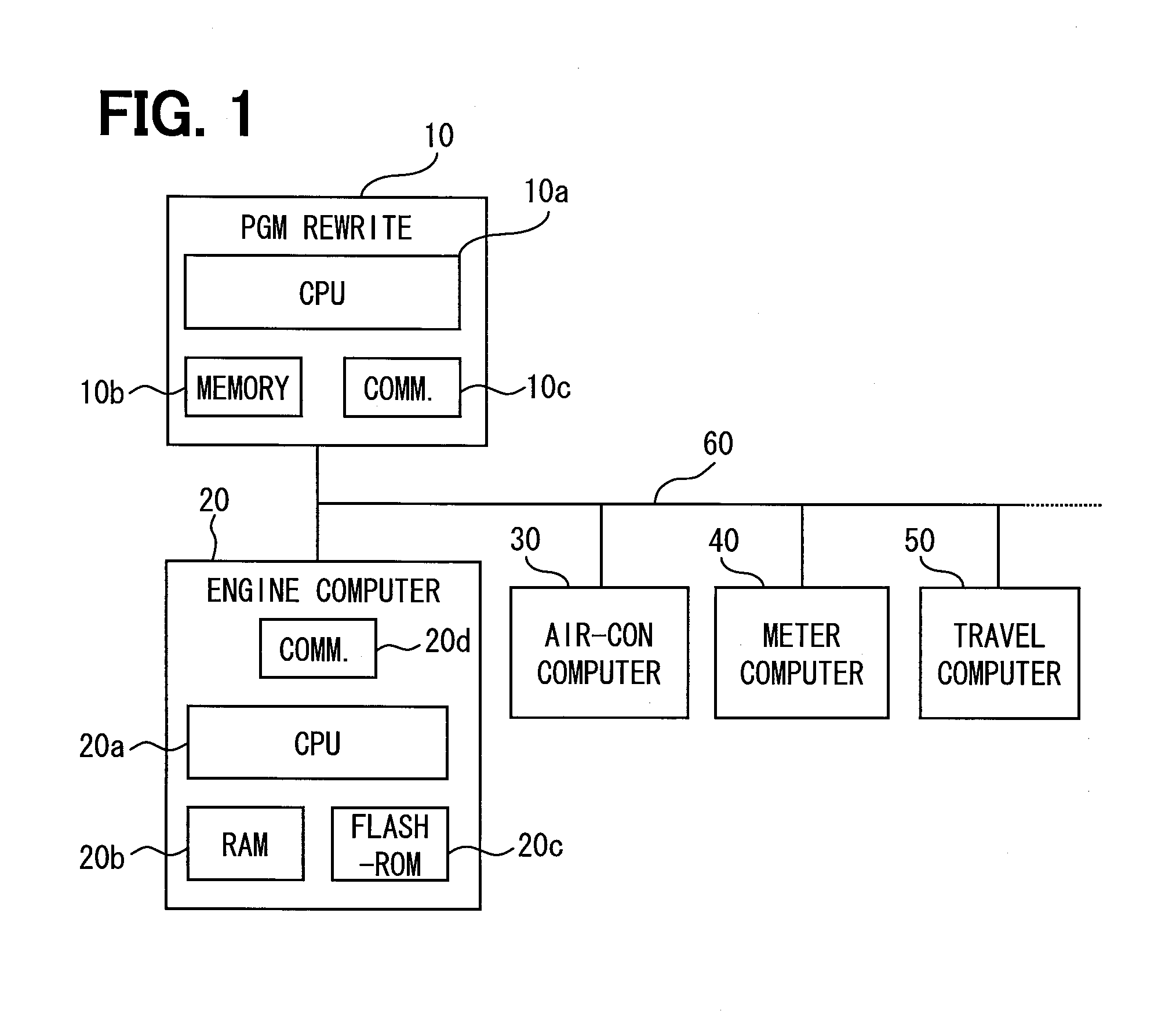
[0027]FIG. 1 illustrates a configuration of a vehicle control system including an engine control computer 20 according to the present embodiment. The vehicle control system includes multiple control computers to control various kinds of in-vehicle instruments such as an engine, air-conditioner, and meter, all of which communicate with each other via a communication network so as to share data and perform coordination control.

[0028]Specifically, the vehicle control system includes an engine control computer 20, an air-conditioner control computer 30, a meter control computer...

second embodiment

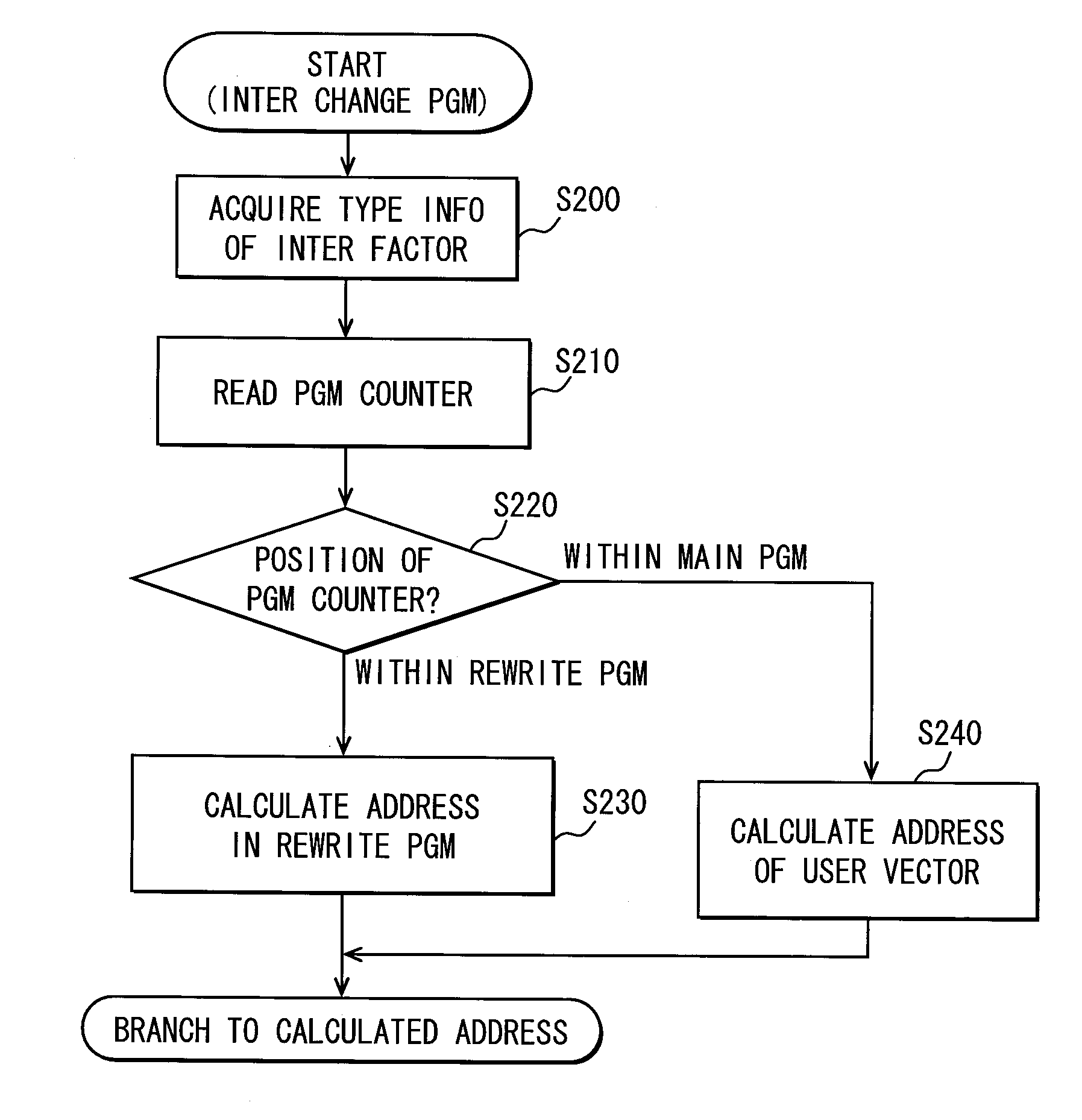
[0053]The following will explain an engine control computer according to a second embodiment of the present disclosure. The engine control computer 20 of the second embodiment has the same configuration as that of the first embodiment; the explanation about the configuration is omitted.

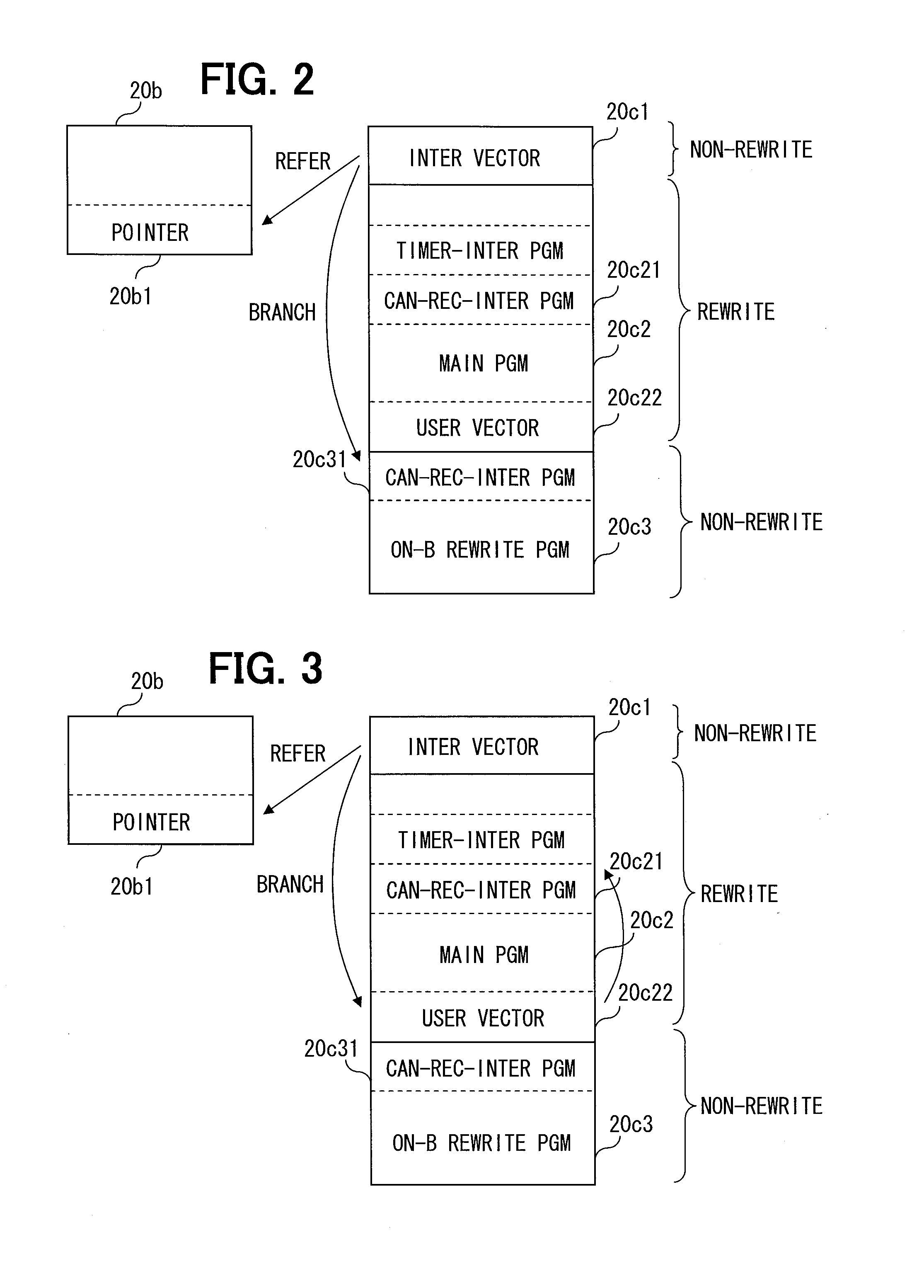
[0054]In the engine control computer 20 according to the first embodiment, when one of the interrupt factors arises, an interrupt vector 20c1 refers to a pointer 20b1 rewritten by the main program or the onboard rewriting program, and provides the CPU 20a with an address (i.e., a CPU-accessed address) of a branch destination.

[0055]The present embodiment does not use those pointers 20b1 in the first embodiment. Instead, the present embodiment is provided with an interrupt changeover program in a non-rewriting area of the flash ROM 20c. Thus, the pointers 20b1 provided in the RAM 20b are not used. This configuration can prevent certainly the processing of the CPU 20a from branching to an unexpected bran...


PUM


Abstract

A rewriting area of a flash ROM stores a main program, which includes a user vector with respect to each of interrupt factors that are different from each other in respect of types. The user vector with respect to a subject interrupt factor indicates an address, which stores an interrupt processing program that is executed when the subject interrupt factor arises. This user vector is stored in a predetermined address dedicated for the subject interrupt factor. The predetermined address of the user vector is enabled to be specified by an interrupt vector or interrupt changeover program, both of which are stored in a non-rewriting area of the flash ROM. Even when an address of the interrupt processing program is changed, the changed address is enabled to be indicated by using the user vector.

Description

CROSS REFERENCE TO RELATED APPLICATION[0001]The present application is based on Japanese Patent Application No. 2012-102250 filed on Apr. 27, 2012, the disclosure of which is incorporated herein by reference.TECHNICAL FIELD[0002]The present disclosure relates to a microcomputer including a rewritable nonvolatile memory storing a main program, the microcomputer performing onboard rewriting of the main program stored in the nonvolatile memory.BACKGROUND ART[0003][Patent Literature 1] JP 2005-228225 A[0004][Patent Literature 2] JP 2002-24043 A[0005]For example, Patent Literature 1 discloses a technology, which avoids a system break-down due to a failure in update of firmware in a memory card adapter containing a rewritable flash memory. Specifically, a flash memory additionally includes a non-rewriting area which stores a program that permits minimum operation even when the firmware update under the onboard state is unsuccessful. Further, the non-rewriting area is additionally provided...

Claims


Application Information

Patent Timeline
Patent Type & Authority Applications(United States)
IPC IPC(8): G06F13/24
CPCG06F13/24
Inventor OGINO, TETSUYA
Owner DENSO CORP
Learn More