
Medical/Dental/Utility Glove with Anti-Fatigue and Ergonomic Improvement

Active Publication Date: 2013-11-07
ANSTEY PAUL
View PDF26 Cites 38 Cited by
  • Summary
  • Abstract
  • Description
  • Claims
  • Application Information

AI Technical Summary

Benefits of technology

The invention is an improved glove that has stress relief zones and reinforced zones to provide support to the hand. The relief zones are designed to match the natural bending of the fingers and thumb, and can also be provided over the webbing between the thumb and palm. This helps keep the glove in place while bending and extending the joints, reducing stress and fatigue. The glove is made using a cost-effective and reliable method. Overall, the invention provides a more comfortable and functional glove for various activities.

Problems solved by technology

This has led to a mismatch between the flex patterns of the gloves and the flexing of the hand of the wearer.
The amount of force required to stretch the glove tends to cause fatigue in the hands of the wearer and can cause other discomfort such as constriction and uncomfortable rubbing / friction along the skin.
Additionally, as the glove stretches on one side of the user, an area elsewhere on the hand may also experience bunching / sagging of the material as it fold on itself, for example, bunching beneath the joint of the fingers.
In addition to the above disadvantages, this can reduce the tactile feel through the glove and interfere with grasping delicate instruments.
A wearer thus often wears ill-fitting (“larger”) gloves than the wearer's hand size to reduce fatigue with disadvantage of bunching at the fingertip or elsewhere than interferes with the grip and with the tactile feedback.
A number of bellows are provided along two fingers of the glove to provide circumferential flex areas as well as too much flexure provided by the bellows causing the fingertips of the gloves to be too loose.
Additionally, the portion of the bellows below the finger (palm side) is unnecessary and in the way causing a hindrance to an operator grasping an instrument, for example.
Unfortunately, this does not remove the problem of the material bunching in the area opposite the flex zone.

Method used


Image

  • Medical/Dental/Utility Glove with Anti-Fatigue and Ergonomic Improvement
  • Medical/Dental/Utility Glove with Anti-Fatigue and Ergonomic Improvement
  • Medical/Dental/Utility Glove with Anti-Fatigue and Ergonomic Improvement

Examples


Embodiment Construction

)

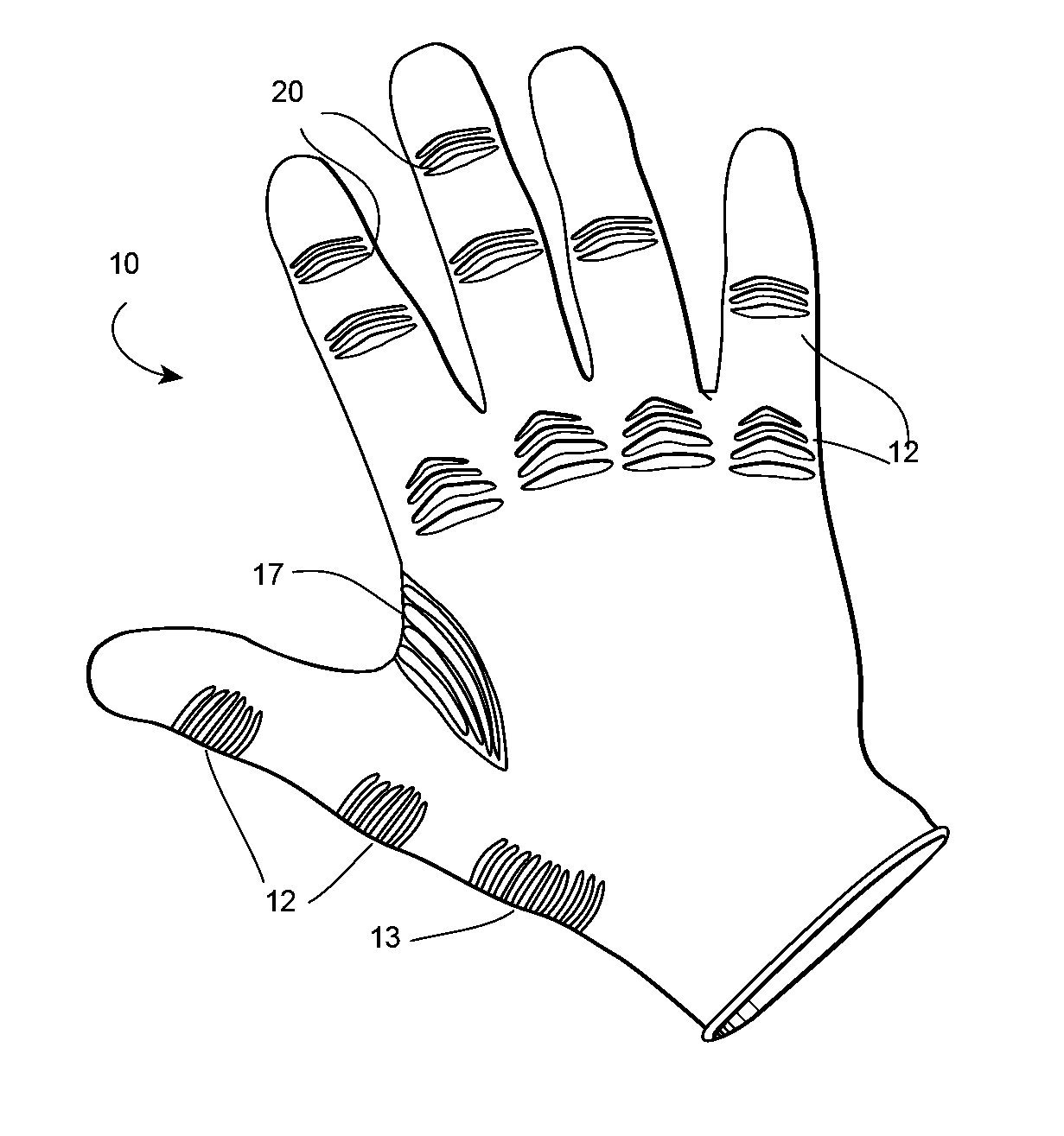
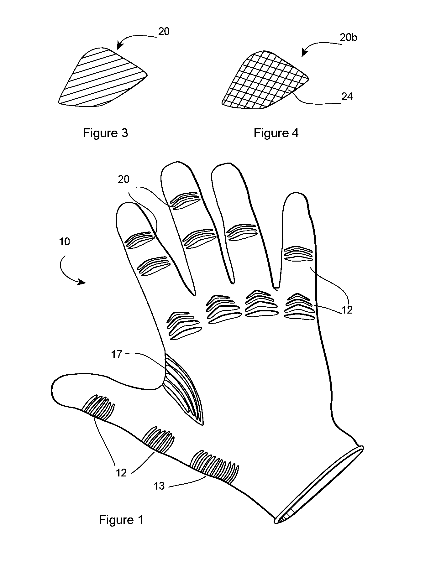
[0027]The present invention according to at least one aspect is to an improve glove having stress relief zones and / or reinforced zones to increase the ergonomics, comfort and usability of the glove.

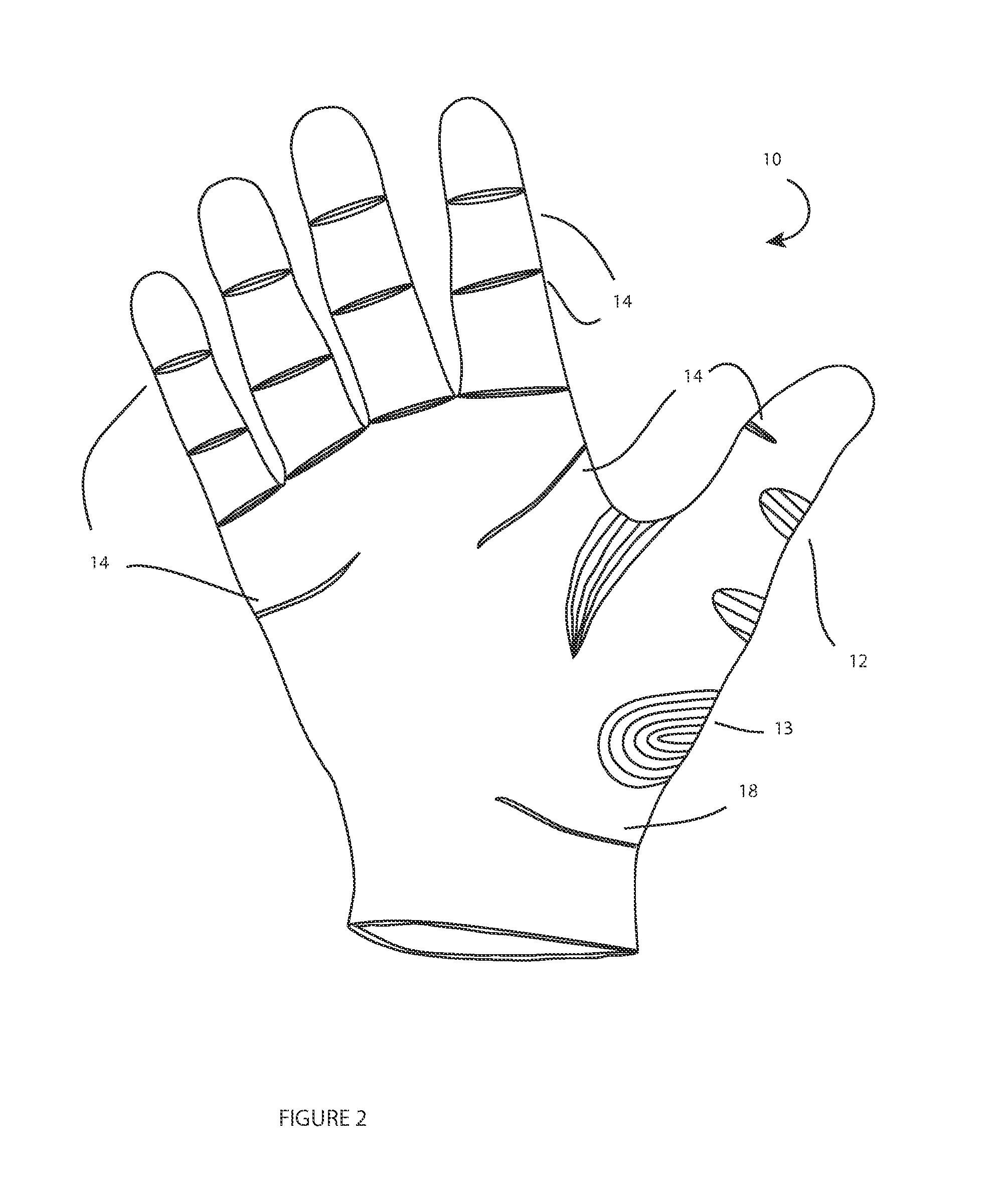
[0028]FIG. 1 shows an exemplary embodiment of the back of a glove 10 according to at least one aspect of the invention. FIG. 2 shows the front (or palm side) of the glove. The different zones on the back are coincidentally stretch zones and the zones on the front are reinforced zones since the hand generally bends in only one direction, except for the thumb.

[0029]In practice, a glove would be constructed of a thin layer of uniform latex, nitril, vinyl or other material. According to a preferred embodiment of the invention, at least one stress relief area 12 is provided above the knuckles (knuckle joints, etc.) of the hand and located within the uniform thickness main glove portion. This stress relief area includes a ribbed or accordion fold (20, FIG. 3) or alternatively diamond cross lin...


PUM


Abstract

The present invention is to an improved glove having both anatomically correlating stress relief zones and / or reinforced zones to add support in areas opposite the stress relief zones to keep bunching or slipping of the glove from interfering with the bending of the user's joints. The glove may have corrugated relief zones over some or all of the joints and knuckles of the hand, wherein the relief zones are formed of peaks and valleys. A relief zone can also be provided over the webbing between the thumb and the palm. The vertical or longitudinal relief zones provide for improved glove quality while keeping manufacturing difficulty and costs at a minimum.

Description

BACKGROUND OF THE INVENTION[0001]1. Field of the Invention[0002]The present application relates to an ergonometrically improved glove having areas near or within natural fold lines of a user's hand with stress relief features to provide lower resistance to flexing and anti-fatigue enhancements.[0003]2. Description of the Prior Art[0004]Latex and other medical gloves are used by medical and / or dental professionals to maintain a sanitary boundary between the medical staff (or other users / operators) and the patient. These gloves have also found their way into non-medical fields such as use by automotive workers, painters, and construction work to reduce the transfer of oils, paints, foams and chemicals onto the worker. The inventions described herein can also be used to increase the usability of sports gloves as well as general gloves for other purposes.[0005]Medical gloves are typically of uniform thickness throughout the glove to maintain a low cost by simplifying production. This ha...

Claims


Application Information

Patent Timeline
IPC IPC(8): A41D19/015
CPCA61B19/04A41D19/0062A41D19/015A61B2017/00424A61B42/00A41D19/0082A41D19/00B29C41/14B29K2995/0046B29L2031/4864B29L2031/753
Inventor ANSTEY, PAUL
Owner ANSTEY PAUL
Features
  • Generate Ideas
  • Intellectual Property
  • Life Sciences
  • Materials
  • Tech Scout
  • Unparalleled Data Quality
  • Higher Quality Content
  • 60% Fewer Hallucinations
Learn More