Evaporator and refrigeration system comprising the same

a technology of evaporator and refrigeration system, which is applied in the field of refrigeration, can solve the problems of reducing the energy efficiency of the system, low defrosting speed, and large resistance of refrigerant, and achieves the effects of improving operation efficiency, short defrosting time, and high defrosting speed

Active Publication Date: 2013-11-07
SANHUA HANGZHOU MICRO CHANNEL HEAT EXCHANGER +1
View PDF6 Cites 3 Cited by
  • Summary
  • Abstract
  • Description
  • Claims
  • Application Information

AI Technical Summary

Benefits of technology

[0008]Embodiments of the invention seek to solve at least one of the problems existing in the related art to at least some extent. Accordingly, an evaporator is provided by which the defrosting time is short, the defrosting speed is high, and the operation efficiency is improved. Further, a refrigeration system comprising the above-mentioned evaporator is provided, which may reduce the fluctuation of indoor temperature.
[0010]With the evaporator according to embodiments of the invention, because the defrosting tube is connected to the first or second header, when the evaporator needs to be defrosted, the refrigerant enters into the first or second header from the defrosting tube, thus increasing the defrosting speed, shortening the defrosting time, and improving the energy efficiency of the refrigeration system.

Problems solved by technology

On the other hand, defrosting will cause indoor-environment-heat supply to be broken off, thus reducing the energy efficiency of the system.
In addition, because refrigerant guide pipes are usually disposed within the inlet header and the outlet header of the evaporator, during defrosting, the flow resistance of the refrigerant is very large, and the refrigerant may not pass through the evaporator in large quantities rapidly such that the defrosting speed is low.
In the refrigeration system using a refrigerant (for example, R407C with large temperature glide), because the frosted position is usually adjacent to the refrigerant inlet of the heat exchanger, defrosting may not be rapidly performed by “reverse-circulation defrosting” mode of introducing the gaseous refrigerant from the outlet header such that the defrosting time is long and the operating efficiency of the system is low.

Method used


Image

  • Evaporator and refrigeration system comprising the same
  • Evaporator and refrigeration system comprising the same
  • Evaporator and refrigeration system comprising the same

Examples


Embodiment Construction

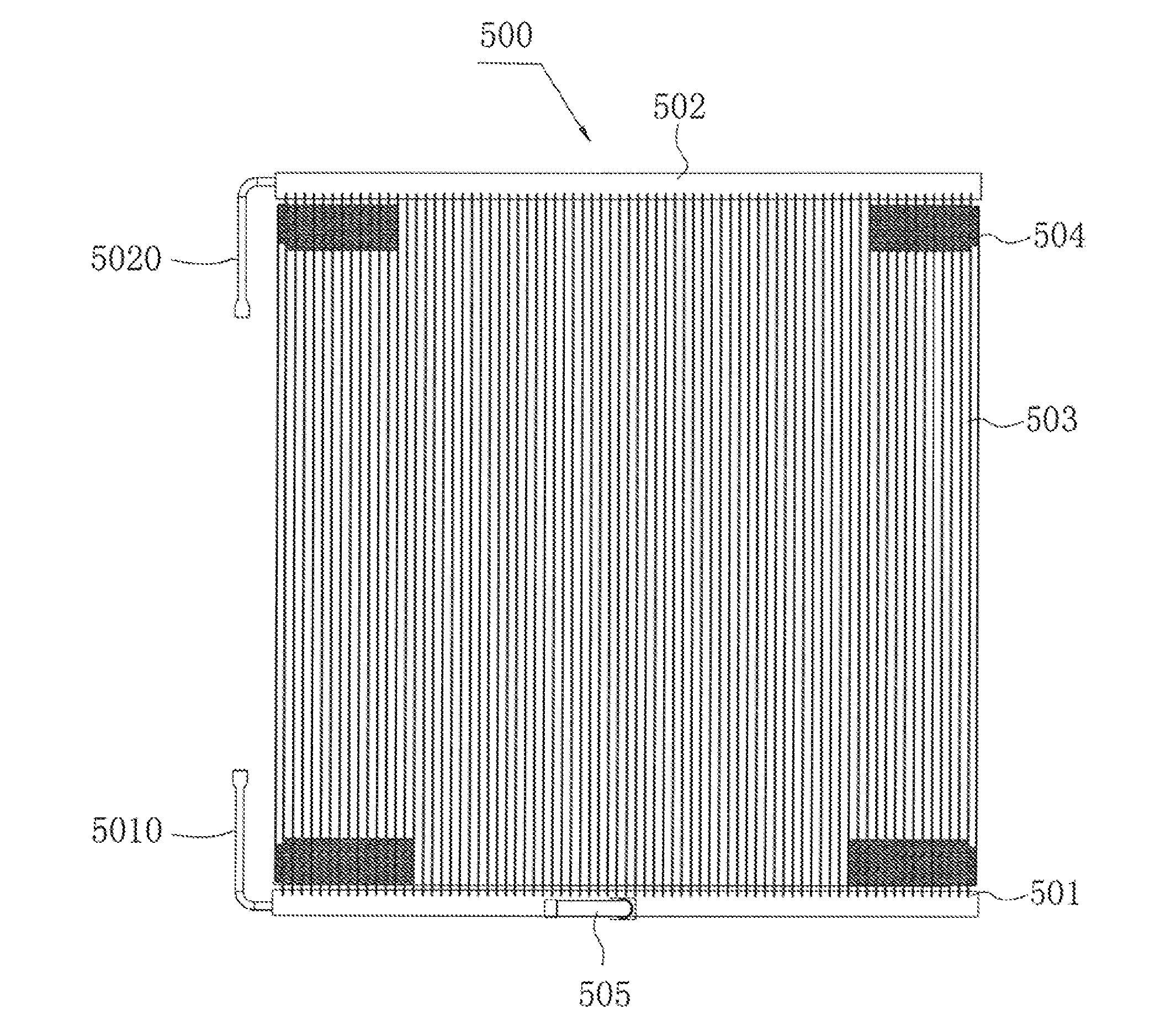
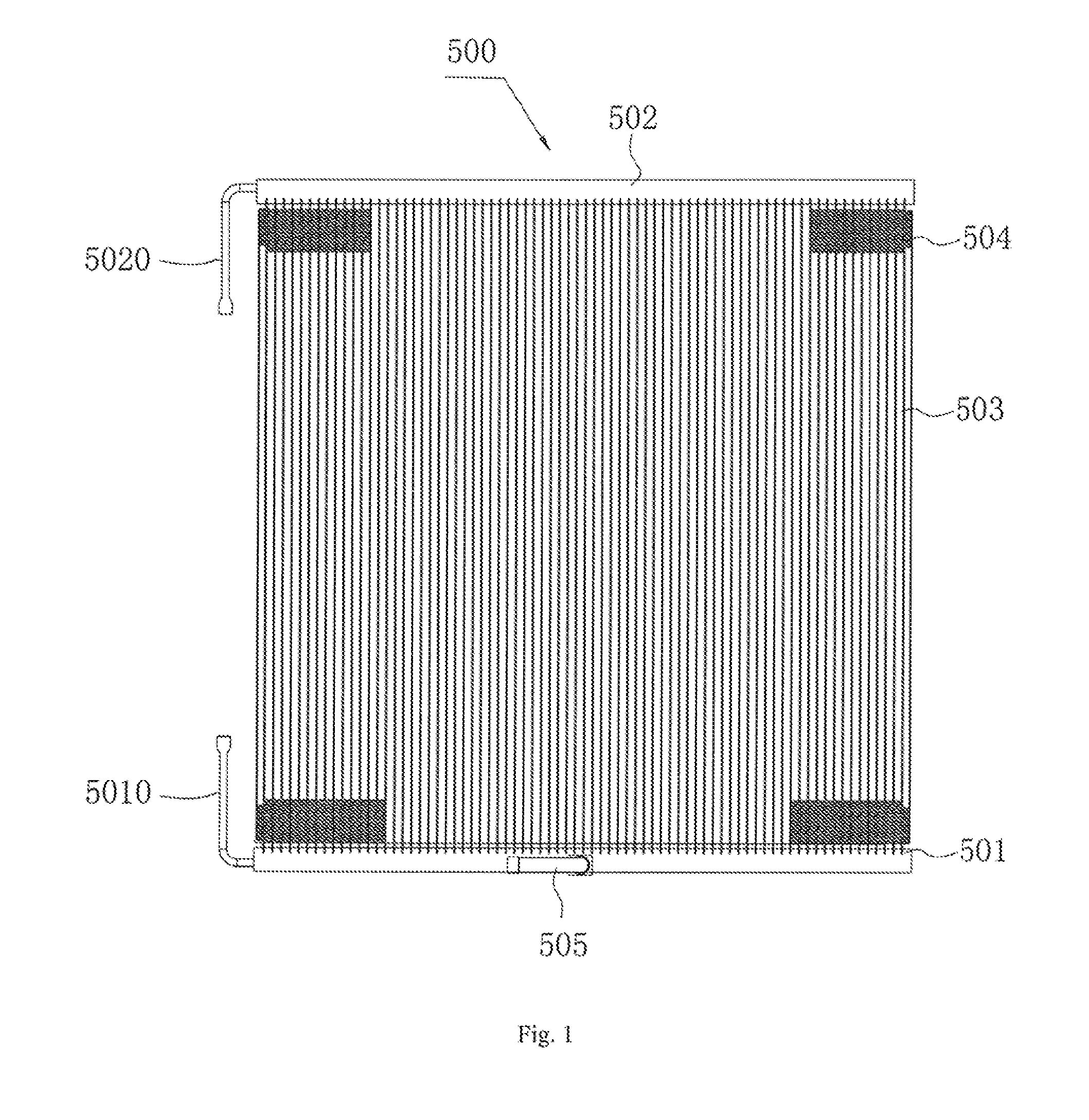
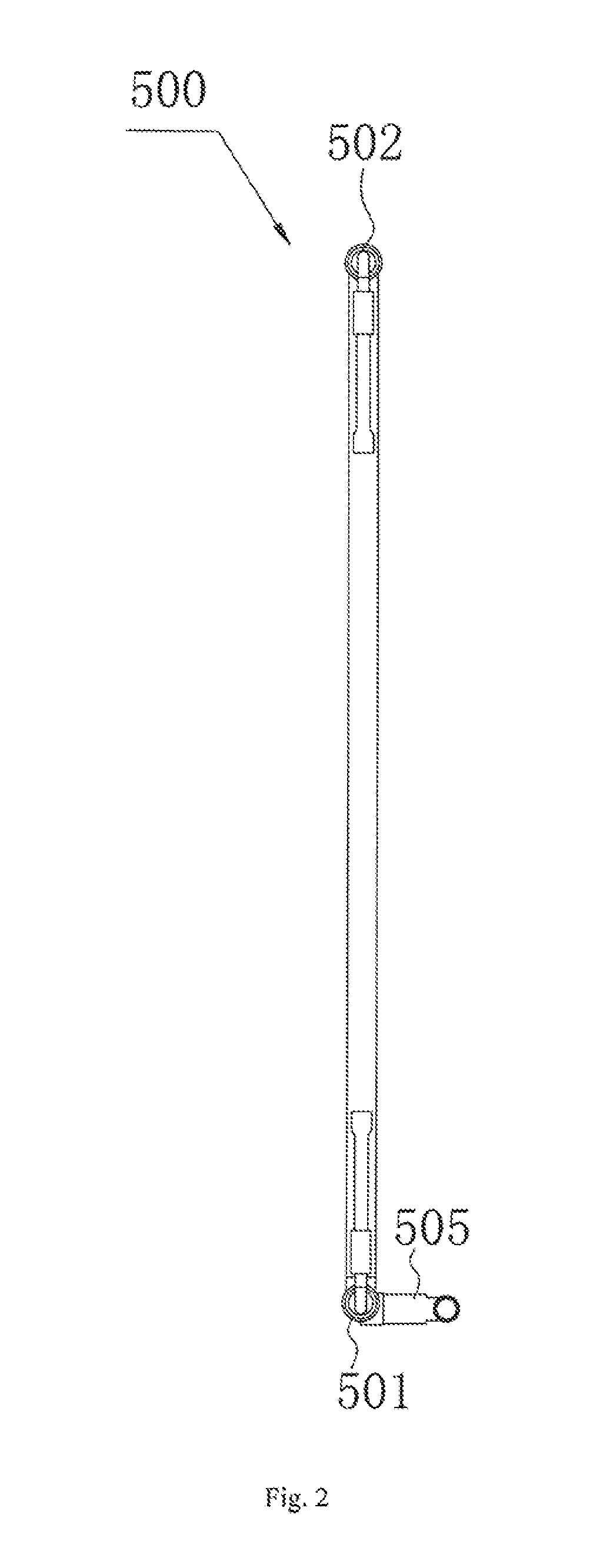
[0031]Embodiments of the invention will be described in detail in the following descriptions examples of which are shown in the accompanying drawing, wherein the same or similar elements and elements having same or similar functions are denoted by like reference numerals throughout the descriptions. The embodiments described herein with reference to the accompanying drawing are explanatory and illustrative, which are used to generally understand the invention. The embodiments shall not be construed to limit the invention.

[0032]It is to be understood that phraseology and terminology used herein with reference to device or element orientation (terms like “longitudinal,”“lateral,”“front,”“rear,”“right,”“left,”“lower,”“upper,”“horizontal,”“vertical,”“above,”“below,”“up,”“top,” and “bottom” as well as derivatives thereof such as “horizontally,”“downwardly,”“upwardly,” etc.) are only used to simplify description of the invention and do not alone indicate or imply that the device or elemen...


PUM


Abstract

An evaporator (500) comprises a first header (501) defining one end formed with a first refrigerant port (5010), a second header (502) defining one end formed with a second refrigerant port (5020), heat-exchange tubes (503) each connected between the headers (501, 502) to communicate the headers (501, 502), fins (504) respectively interposed between adjacent heat-exchange tubes (503), and a defrosting tube (505) defining a first end connected to one of the headers (501, 502) to communicate with an interior of the one header. A position of the first end of the defrosting tube (505) is spaced apart from the one end of the one header by a predetermined distance. A refrigeration system comprises the evaporator. By providing the defrosting tube (505), defrosting speed is increased, defrosting time is shortened, and energy efficiency of the refrigeration system is improved.

Description

CROSS-REFERENCE TO RELATED APPLICATIONS[0001]This is a “national phase” application of International Patent Application PCT / CN2010 / 080259 filed on Dec. 24, 2010, which, in turn, is based upon and claims priority to Chinese Patent Application 201010538204.2 filed Nov. 4, 2010.BACKGROUND OF INVENTION[0002]1. Field of Invention[0003]The invention relates to, in general, refrigeration and, more particularly, an evaporator and a refrigeration system comprising the evaporator.[0004]2. Description of Related Art[0005]When a refrigeration system, such as the refrigeration system of an air conditioner, is operated in winter and the ambient temperature is very low, the evaporating temperature of the evaporator will be less than zero degrees, and, consequently, the refrigeration system needs to be defrosted. With the conventional refrigeration system, full reverse circulation is used for defrosting; that is, the condenser is used as an evaporator, and the evaporator is used as a condenser.[000...

Claims


Application Information

Patent Timeline
Patent Type & Authority Applications(United States)
IPC IPC(8): F25B39/02
CPCF25B39/02F25B47/025F28D1/05316F28D2021/0071F28D2021/0085F28F9/0273F28F17/00F28F19/006F25B47/00F28D1/053F25B47/006F25B47/02F25B47/022F25B2313/02322F25B2347/02F25D21/06
Inventor GAO, QIANGLI, YANXING
Owner SANHUA HANGZHOU MICRO CHANNEL HEAT EXCHANGER
Why Eureka
Try Eureka