Differential pressure gauge

Active Publication Date: 2013-11-07
GAMMON JAMES H
View PDF5 Cites 28 Cited by
  • Summary
  • Abstract
  • Description
  • Claims
  • Application Information

AI Technical Summary

Benefits of technology

The present invention is a differential pressure gauge with a remote indicator that reduces errors, improves reliability, and is resistant to magnetic contaminants. Additionally, it is cost-effective to manufacture.

Problems solved by technology

There are, however, many disadvantages to housing the piston in a glass tube.
One common problem is that the glass tube and the piston must each be formed from materials having a similar coefficient of thermal expansion for the piston to retain its close fitting relationship within the glass tube, especially when the piston-type gauge experiences a wide range of temperatures during use.
Unfortunately, those materials available for forming the piston to have a coefficient of thermal expansion similar to that of glass are typically expensive metallic alloys, such as Invar 36, that greatly increases the cost of the piston-type gauge.
These high cost metallic alloys are also problematic as they often are difficult to machine without causing serious burring in the metallic alloy, which in turn affects the quality of the seal between the piston and the glass tube.
Another problem associated with the use of a glass tube as a housing for the piston is that the strength of a glass tube decreases as a selected diameter of the glass tube is increased, prohibiting the piston-type gauge from utilizing a larger diameter glass tube if high internal pressures act on the glass tube.
Accordingly, larger diameter glass tubes fail due to wall tension at lower internal pressures than do smaller diameter glass tubes.
This in turn limits the accuracy of the differential pressure reading.
Smaller dimensioned parts introduce a greater percentage of error than do larger dimensioned parts.
However, disadvantages of using a piston displayed through a magnetic sensor include expensive materials and manufacturing processes, increased errors due to damage or interference from the presence of contaminants of a magnetic nature between the piston and the cylinder, and a general decrease in the accuracy of the pressure difference readings due to unnecessary components.

Method used


Image

  • Differential pressure gauge
  • Differential pressure gauge

Examples


Embodiment Construction

[0017]The following detailed description and appended drawing describe and illustrate an exemplary embodiment of the invention. The description and drawing serve to enable one skilled in the art to make and use the invention, and are not intended to limit the scope of the invention in any manner.

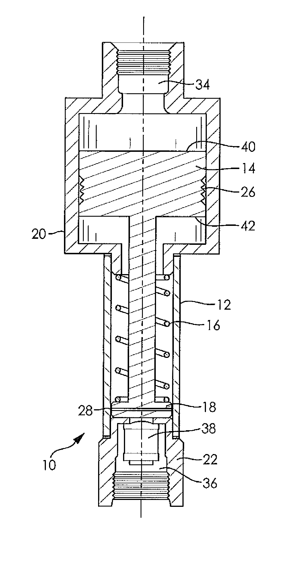
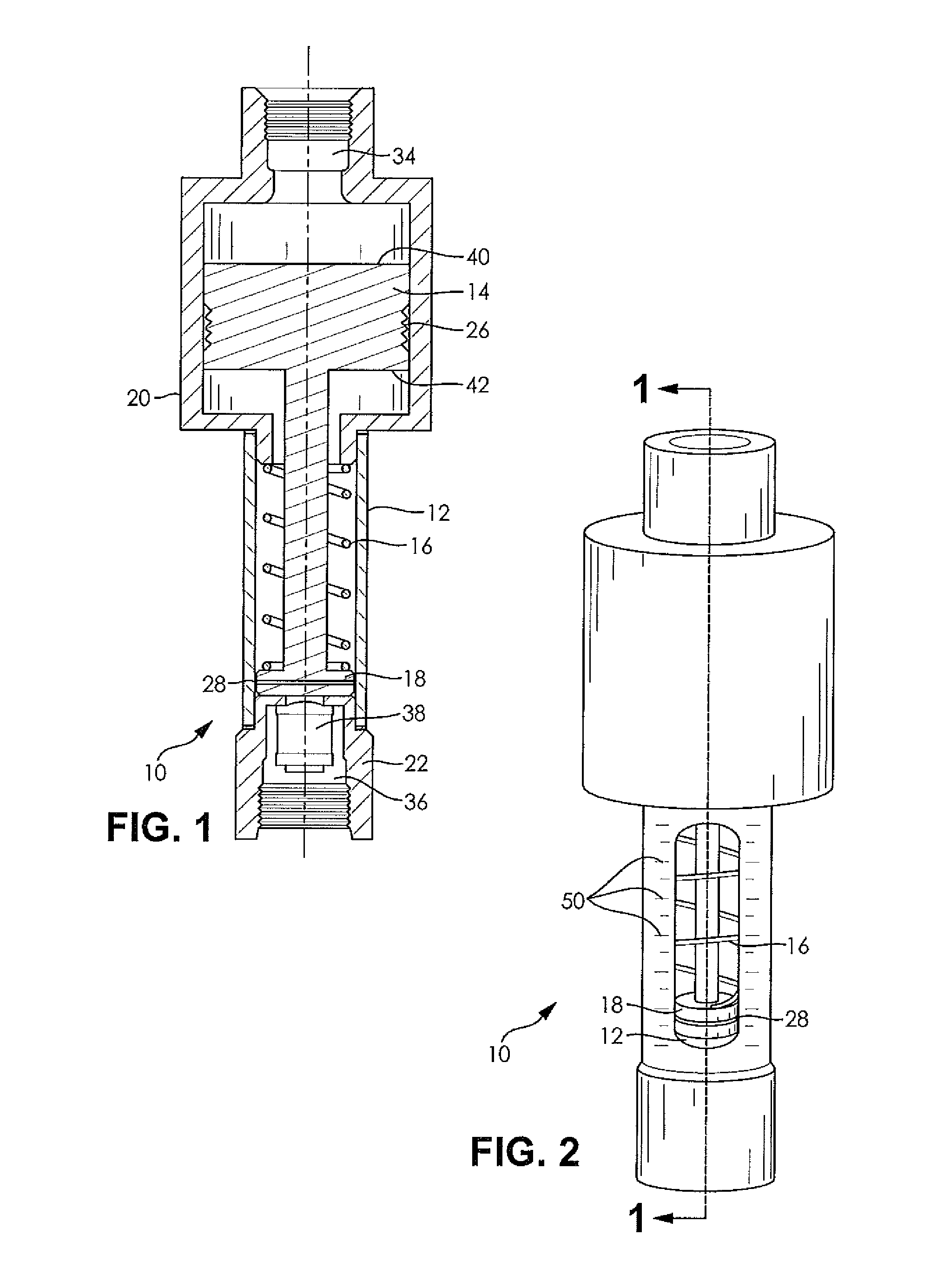
[0018]Referring to FIG. 1, there is illustrated a differential pressure gauge incorporating the features of the disclosure, generally indicated by reference numeral 10. The differential pressure gauge 10 includes a cylinder 12, a piston 14, a spring 16, and a remote indicator 18. The differential pressure gauge 10 also includes a first housing member 20 and a second housing member 22.

[0019]The cylinder 12 is hollow and open at each of two spaced apart ends. The cylinder 12 may be any size and shape appropriate for housing the spring 16 and the remote indicator 18. However, it may be preferable for an outer diameter of the cylinder 12 to be minimized because hollow cylindrical vessels withsta...


PUM


Abstract

A pressure gauge including a hollow cylinder, a first housing member having a first pressure inlet disposed at a first end of the cylinder, and a second housing member having a second pressure inlet disposed at a second end of the cylinder. The pressure gauge also includes a piston slidably disposed in the first housing member. The piston includes a remote indicator coupled to an end of the piston. At least a portion of the remote indicator extends into the hollow cylinder. A spring is disposed in the cylinder abutting the remote indicator and urges the remote indicator toward the second housing member. An increased pressure difference between the first pressure inlet and the second pressure inlet causes the remote indicator to move away from the second housing member and toward the first housing member, and the remote indicator provides a measure of the pressure difference relative to indicia included on the pressure gauge.

Description

CROSS-REFERENCE TO RELATED APPLICATION[0001]This application claims priority to U.S. Provisional Application Ser. No. 61 / 640,832, filed May 1, 2012, the entire disclosure of which is hereby incorporated herein by reference.FIELD OF THE INVENTION[0002]The present disclosure relates to a differential pressure gauge and more particularly to a gauge for measuring and displaying differential pressure using a remote indicator.BACKGROUND OF THE INVENTION[0003]It is often beneficial to monitor the condition of filter elements. One of the most common ways to monitor the condition of filter elements is to measure a pressure drop across a filter vessel using a differential pressure gauge. A measurable difference in pressure occurs over time because, in a clean filter, a fluid being filtered flows freely without restriction, and in a filter filled with dirt and debris, the fluid flow is restricted. Accordingly, a fluid flowing through a clogged filter will have a higher pressure before entering...

Claims


Application Information

Patent Timeline
IPC IPC(8): G01L7/16
CPCG01L7/16G01L13/02G01L19/10G01L19/143
Inventor GAMMON, JAMES H.
Owner GAMMON JAMES H
Why Eureka
Try Eureka