Tunneling-junction solar cell with shallow counter doping layer in the substrate

a solar cell and counter-doping technology, applied in the field of tunneling junction solar cells, can solve the problems of low short-circuit (jsub>sc/sub>) current of tunneling-based heterojunction devices, and the need for cleaner, cheaper alternative energy sources, and achieve the effect of plasma-enhanced chemical-vapor deposition

Inactive Publication Date: 2013-11-14
SOLARCITY
View PDF4 Cites 27 Cited by
  • Summary
  • Abstract
  • Description
  • Claims
  • Application Information

AI Technical Summary

Benefits of technology

The present invention provides a tunneling-junction solar cell that has improved efficiency. The solar cell includes a base layer, emitter layer, surface field layer, front-side electrode, and back-side electrode. The base layer has a conduction doping type that is opposite to the rest of the base layer. The emitter layer has a wider bandgap than the base layer and a graded doping concentration. The surfaces of the base layer and emitter layer are dressed to optimize light absorption. The solar cell may also include a first quantum-tunneling-barrier layer and a second quantum-tunneling-barrier layer between the base layer and emitter layer. The emitter layer and surface field layer may include amorphous-Si, polycrystalline Si, or wide bandgap semiconductor materials. The solar cell may be designed for maximum sunlight absorption and may be useful for photovoltaic applications.

Problems solved by technology

The negative environmental impact caused by the use of fossil fuels and their rising cost have resulted in a dire need for cleaner, cheaper alternative energy sources.
However, these tunneling-based heterojunction devices often suffer from a lower short-circuit (Jsc) current because the tunneling barrier inevitably blocks the flow of majority carriers.

Method used


Image

  • Tunneling-junction solar cell with shallow counter doping layer in the substrate
  • Tunneling-junction solar cell with shallow counter doping layer in the substrate
  • Tunneling-junction solar cell with shallow counter doping layer in the substrate

Examples


Embodiment Construction

[0033]The following description is presented to enable any person skilled in the art to make and use the embodiments, and is provided in the context of a particular application and its requirements. Various modifications to the disclosed embodiments will be readily apparent to those skilled in the art, and the general principles defined herein may be applied to other embodiments and applications without departing from the spirit and scope of the present disclosure. Thus, the present invention is not limited to the embodiments shown, but is to be accorded the widest scope consistent with the principles and features disclosed herein.

Overview

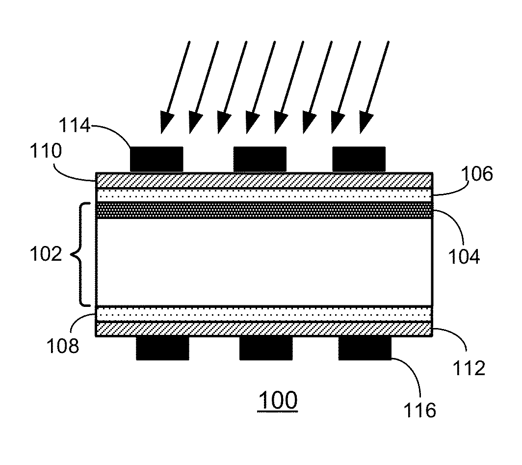
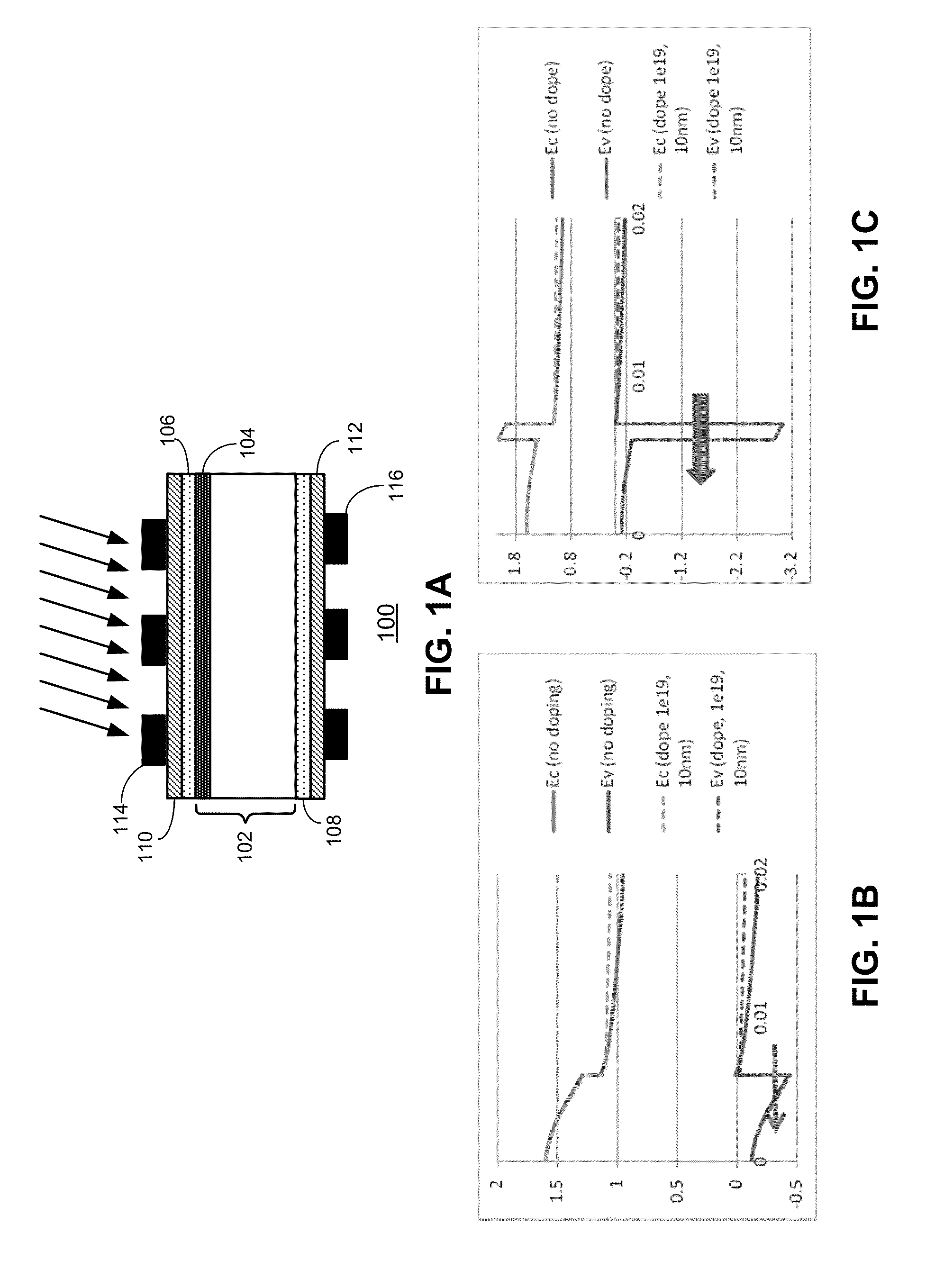
[0034]Embodiments of the present invention provide a crystalline-Si (c-Si)-based solar cell having a shallow counter doping layer situated in the c-Si substrate. The solar cell further includes a quantum-tunneling barrier (QTB) layer. The counter doping can be achieved by doping the surface of the c-Si with a dopant that has an opposite conduction ...


PUM


Abstract

One embodiment of the present invention provides a tunneling junction solar cell. The solar cell includes a base layer, an emitter layer situated adjacent to the shallow counter doping layer, a surface field layer situated adjacent to a side of the base layer opposite to the shallow counter doping layer, a front-side electrode, and a back-side electrode. The base layer includes a shallow counter doping layer having a conduction doping type that is opposite to a remainder of the base layer. The emitter layer has a bandgap that is wider than that of the base layer.

Description

RELATED APPLICATION[0001]This application claims the benefit of U.S. Provisional Application No. 61 / 646,706, Attorney Docket Number SSP12-1002PSP, entitled “Shallow Counter Doping Layer in C—Si Substrate to Improve Performance on Tunneling Heterojunction Solar Cells,” by inventors Zhigang Xie, Jiunn Benjamin Heng, Jianming Fu, and Zheng Xu, filed 14 May 2012.[0002]The subject matter of this application is related to the subject matter of U.S. patent application Ser. No. 12 / 945,792 (Attorney Docket Number SSP10-1002US), entitled “Solar Cells with Oxide Tunneling Junctions,” by inventors Jiunn Benjamin Heng, Chentao Yu, Zheng Xu, and Jianming Fu, filed 12 Nov. 2010, the disclosure of which is incorporated by reference in its entirety herein.BACKGROUND[0003]1. Field[0004]This disclosure is generally related to solar cells. More specifically, this disclosure is related to a tunneling junction solar cell that has a shallow counter doping layer in the substrate.[0005]2. Related Art[0006]T...

Claims


Application Information

Patent Timeline
IPC IPC(8): H01L31/0352H01L31/18
CPCH01L31/035272H01L31/072H01L31/0747H01L31/1804Y02E10/547Y02P70/50
Inventor XIE, ZHIGANGHENG, JIUNN BENJAMINFU, JIANMINGXU, ZHENG
Owner SOLARCITY
Why Eureka
Try Eureka