Seat adjustment device, and vehicle seat device with the seat adjustment device
a technology for vehicle seats and adjustment devices, which is applied in the direction of vehicle components, vehicle arrangements, domestic applications, etc., can solve the problems enlargement of the entire apparatus, and achieve the effects of increasing the thickness of plates, enlargement of the entire apparatus, and sufficient strength
- Summary
- Abstract
- Description
- Claims
- Application Information
AI Technical Summary
Benefits of technology
Problems solved by technology
Method used
Image
Examples
first embodiment
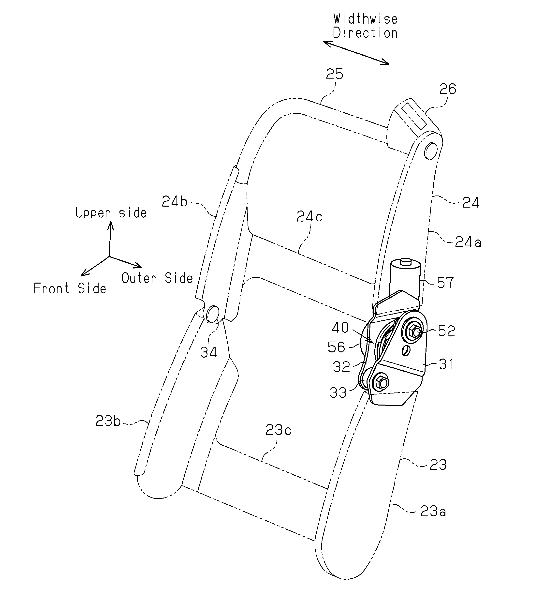
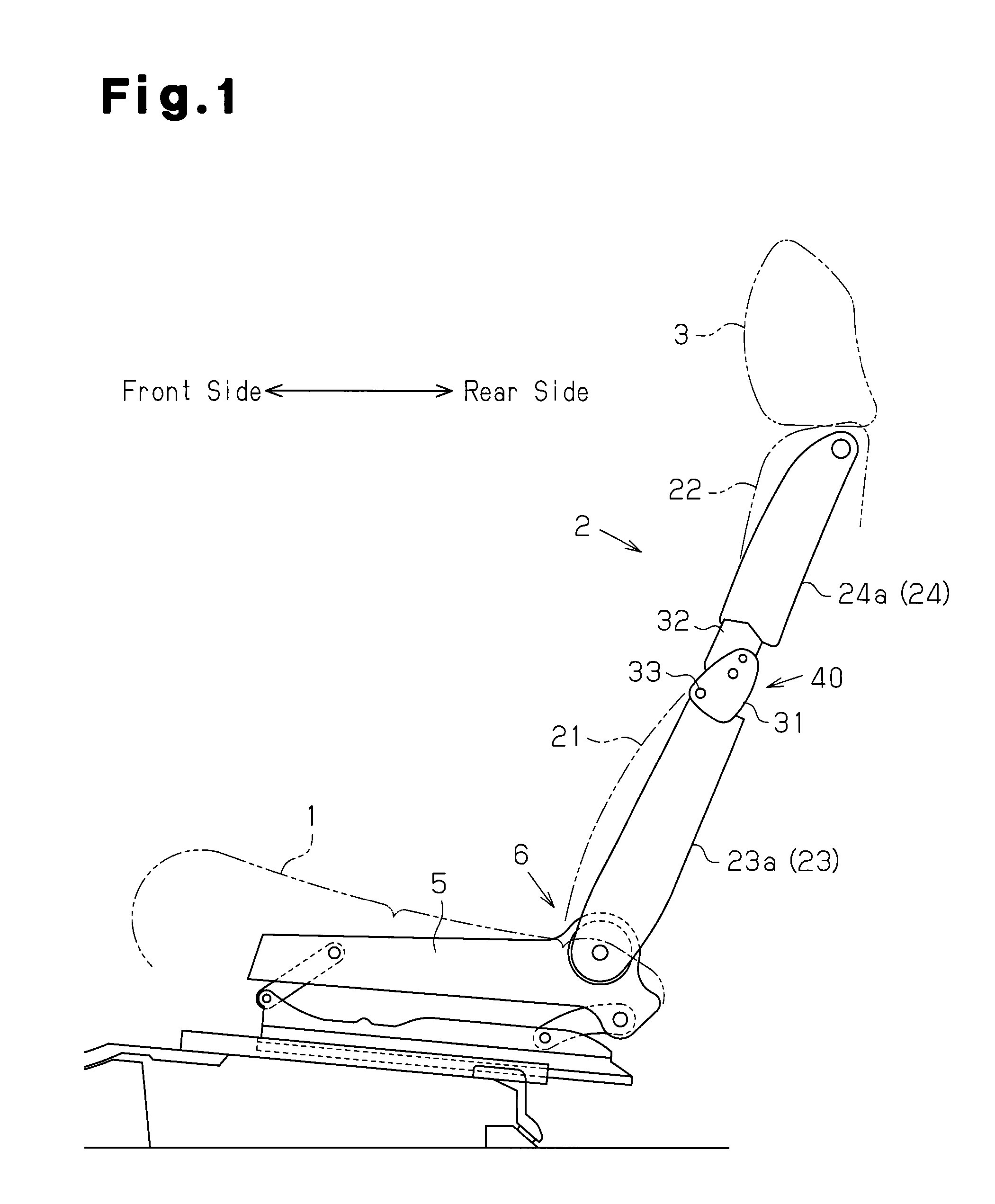
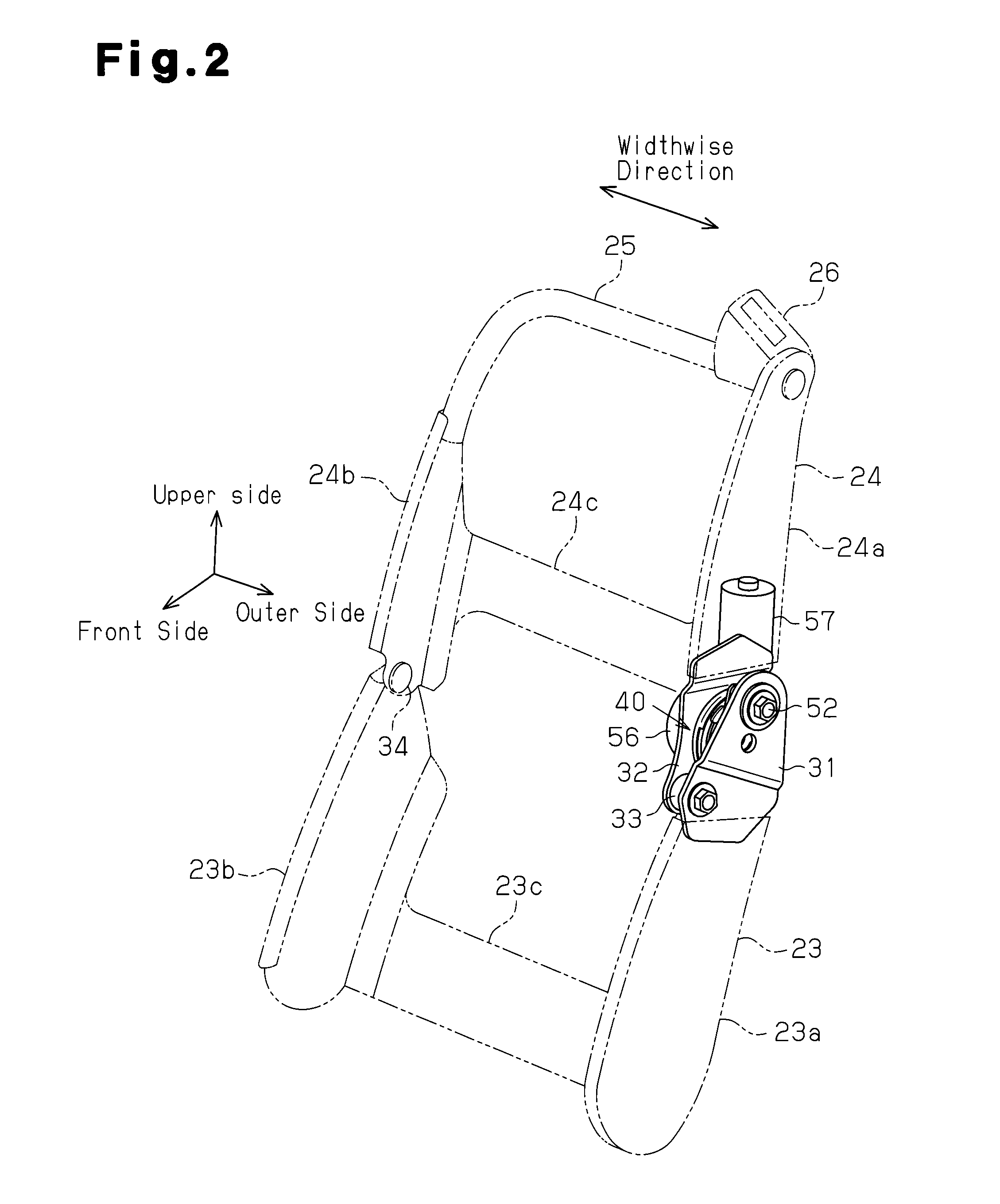
[0020]A first embodiment of the present invention will be described with reference to FIG. 1. As shown in FIG. 1, a vehicle seat apparatus, which is mounted as a front seat in a vehicle such as an automobile, for example, includes a seat cushion 1, which forms a seating portion, having a rear end that supports a lower end of a seat back 2, which forming a backrest, so that the seat back 2 is tiltable in a front to rear direction. The seat back 2 is divided into a lower seat back 21, which is capable of supporting the waist of a vehicle occupant, and an upper seat back 22, which is capable of supporting a blade bone of the vehicle occupant. The seat back 2 is supported by the rear end of the seat cushion 1 at a lower end of the lower seat back 21 so that the seat back 2 is tiltable in the front to rear direction. A headrest 3 for supporting the head of a vehicle occupant is arranged on an upper end of the seat back 2 (upper seat back 22) so that the headrest 3 is movable upward and d...
second embodiment
[0059]A second embodiment of the present invention will now be described with reference to FIG. 6. In the second embodiment, only the structure for absorbing changes in the eccentric amount of the axis of the pivot portion 43 relative to the axis of the hinge shaft 33 is modified from the first embodiment. Therefore, similar components will not be described in detail.
[0060]As shown in FIG. 6, a lower member 61, which serves as a second seat member and a lower frame formed from metal plate, for example, is welded and fixed to an upper end of an outer surface in the widthwise direction of the lower side frame 23a. A circular bearing hole 62, which serves as a bearing portion, is formed in an upper end of the lower member 61. The bearing hole 62 opens toward the guide pin 52 and has an inner diameter that is sufficiently larger than an outer diameter of the guide pin 52 (shaft portion 52b). An eccentric bushing 63, which serves as a shaft member, is attached to the bearing hole 62. The...
third embodiment
[0072]A third embodiment of the present invention will now be described with reference to FIG. 8. In the third embodiment, only the structure for absorbing changes in the eccentric amount of the axis of the pivot portion 43 relative to the axis of the hinge shaft 33 is modified from the first embodiment. Therefore, similar components will not be described in detail.
[0073]As shown in FIG. 8, a lower member 71, which serves as a second seat member and a lower frame formed from metal plate, for example, is welded and fixed to the upper end of the outer surface in the widthwise direction of the lower side frame 23a. The lower member 71 is pivotally coupled to an elongated rod member 72 formed from metal plate, for example. That is, a circular coupling hole 73 is formed in the lower member 71 behind the bearing hole 31a. A substantially stepped cylindrical support pin 74 is fixed to the coupling hole 73. The support pin 74 extends through the coupling hole 73 in the widthwise direction. ...
PUM
 Abstract
Description
Claims
Application Information
 - R&D
- Intellectual Property
- Life Sciences
- Materials
- Tech Scout
- Unparalleled Data Quality
- Higher Quality Content
- 60% Fewer Hallucinations
Browse by: Latest US Patents, China's latest patents, Technical Efficacy Thesaurus, Application Domain, Technology Topic, Popular Technical Reports.
© 2025 PatSnap. All rights reserved.Legal|Privacy policy|Modern Slavery Act Transparency Statement|Sitemap|About US| Contact US: help@patsnap.com


