
Cellscope apparatus and methods for imaging

a cellscope and apparatus technology, applied in the field of cellscope apparatus and methods for enhanced imaging with mobile electronics devices, can solve the problems of inconvenient use, inconvenient use, and inability to meet the needs of patients, and achieve the effect of enhancing imaging

Active Publication Date: 2013-11-14
RGT UNIV OF CALIFORNIA
View PDF26 Cites 85 Cited by
  • Summary
  • Abstract
  • Description
  • Claims
  • Application Information

AI Technical Summary

Benefits of technology

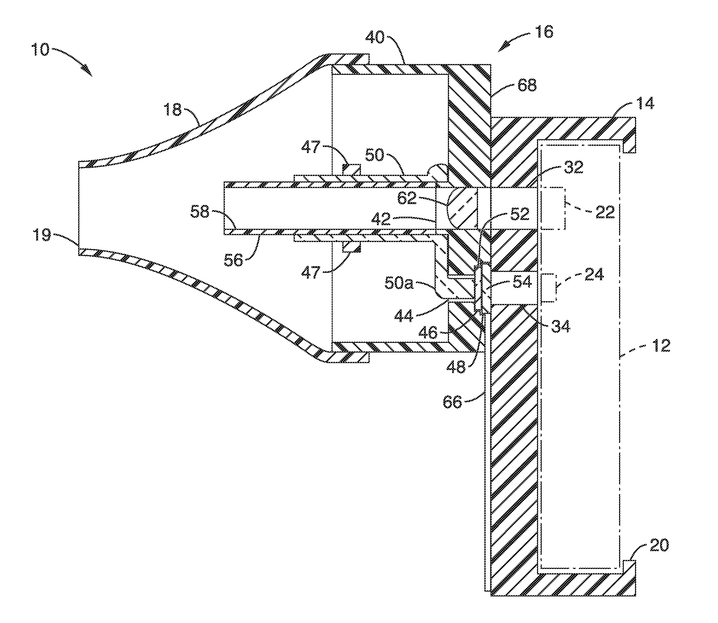
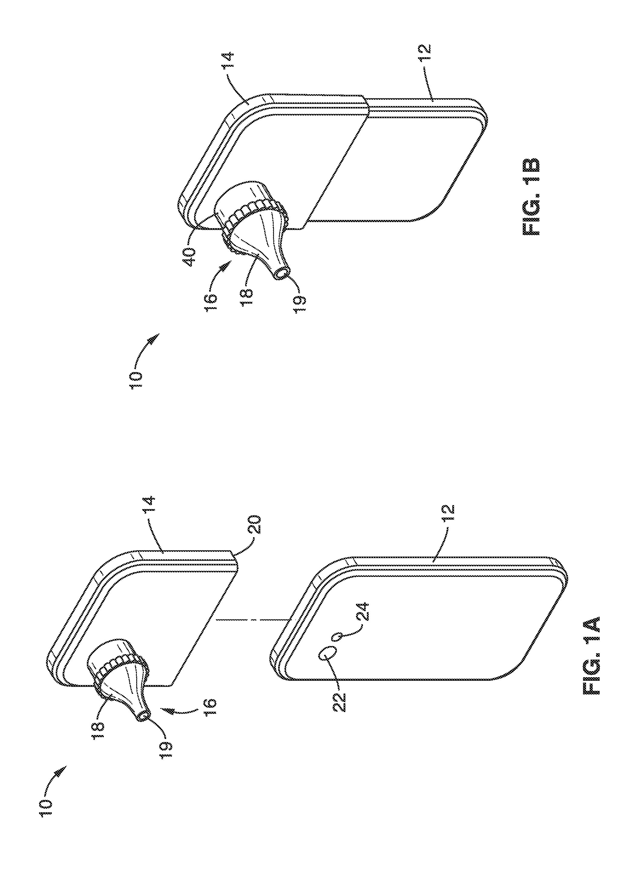
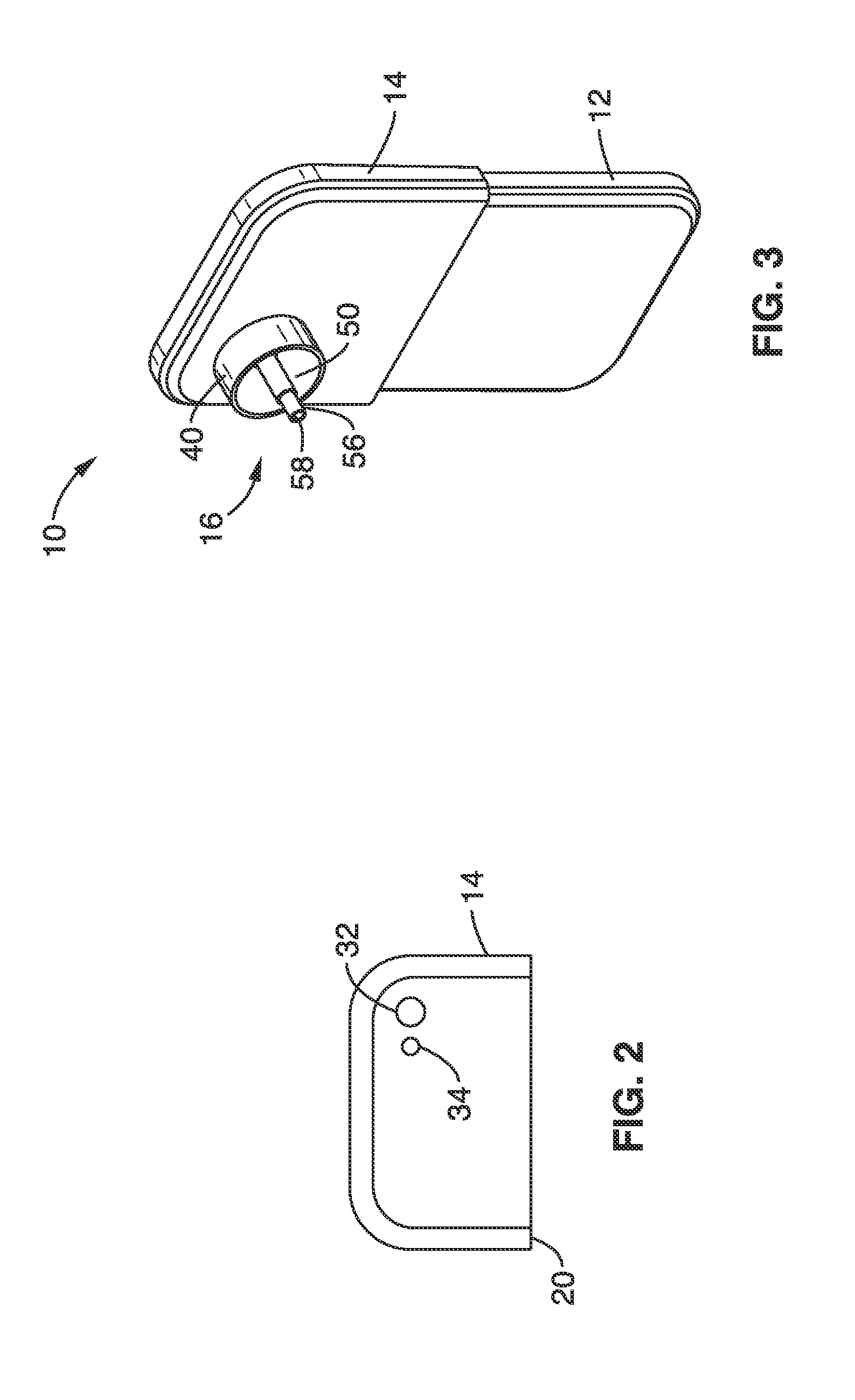
The present invention introduces an improved system and method for enhancing imaging using wireless transmission devices with a camera, such as a mobile phone, combined with an optical attachment. This leads to better quality images that can be viewed, analyzed, and used for various applications including diagnosis and product recommendations. The system comprises a releasable optical assembly with an attachment surface for releasably coupling the optical assembly to the wireless device and an optical transmission element that enhances the image captured by the built-in camera of the wireless device prior to its reception. A programming executable on the wireless device or other external device is used for receiving and post-processing the enhanced image.

Problems solved by technology

However, the cameras and illumination sources included with most mobile electronic devices are primitive with respect to the type of imaging that may be required for special surfaces such as a patient's skin or body passage.
Many common medical tests may be performed using telemedicine, but stand-alone devices used by physicians are often too expensive or specialized to appeal to consumers.

Method used


Image

  • Cellscope apparatus and methods for imaging
  • Cellscope apparatus and methods for imaging
  • Cellscope apparatus and methods for imaging

Examples


embodiment 1

[0090]2. The apparatus of embodiment 1, wherein the optical transmission element comprises a first optical transmission element configured to magnify the image.

embodiment 2

[0091]3. The apparatus of embodiment 2, wherein the optical transmission element comprises a second optical transmission element configured to enhance illumination of the image.

embodiment 3

[0092]4. The apparatus of wherein the first optical transmission element comprises a lens; the housing configured to house the lens in an alignment within an optical path of the built-in camera.


PUM


Abstract

An improved system and methods for enhancing the imaging of cameras included with wireless mobile devices, such as cellular phone or tablets. The imaging system includes a releasable optical attachment for imaging skin surfaces and cavities of the body. The releasable optical attachment comprises optical enhancement elements such as magnifying lenses, illumination diverting elements, and filters. Images can be viewed and analyzed on the mobile device, or transmitted to another location / device for analysis by a person or software. The results can be used to provide diagnosis, or for a variety of other applications including image comparison over time and product recommendations.

Description

CROSS-REFERENCE TO RELATED APPLICATIONS[0001]This application is a 35 U.S.C. §111(a) continuation of PCT international application number PCT / US2011 / 058466 filed on Oct. 28, 2011, incorporated herein by reference in its entirety, which is a nonprovisional of U.S. provisional patent application Ser. No. 61 / 532,617 filed on Sep. 9, 2011, incorporated herein by reference in its entirety, and a nonprovisional of U.S. provisional patent application Ser. No. 61 / 408,568 filed on Oct. 29, 2010, incorporated herein by reference in its entirety.[0002]The above-referenced PCT international application was published as PCT International Publication No. WO 2012 / 058641 on May 3, 2012 and republished on Jul. 5, 2012, and is incorporated herein by reference in its entirety.[0003]This application is related to U.S. patent application Ser. No. 12 / 826,375 filed on Jun. 29, 2010, incorporated herein by reference in its entirety, which claims priority from, and is a 35 U.S.C. §111(a) continuation of, PC...

Claims


Application Information

Patent Timeline
Patent Type & Authority Applications(United States)
IPC IPC(8): H04N5/225
CPCH04N5/2254H04M1/21H04N17/002A61B1/00108A61B1/227G02B25/002A61B1/042A61B1/00052H04N23/57H04N23/55A61B1/044A61B5/0077
Inventor FLETCHER, DANIELDOUGLAS, ERIKSHENG, AMYLAM, WILBURMAAMARI, ROBI
Owner RGT UNIV OF CALIFORNIA
Learn More