Encoding and decoding based on blending of sequences of samples along time

a sequence and sequence technology, applied in image data processing, television systems, instruments, etc., can solve the problems of prone to artifacts, affecting the quality of images blended, and accumulating errors in samples, so as to achieve the effect of maximizing the time correlation of images blended

Active Publication Date: 2013-11-14
V NOVA INT LTD
View PDF1 Cites 28 Cited by
  • Summary
  • Abstract
  • Description
  • Claims
  • Application Information

AI Technical Summary

Benefits of technology

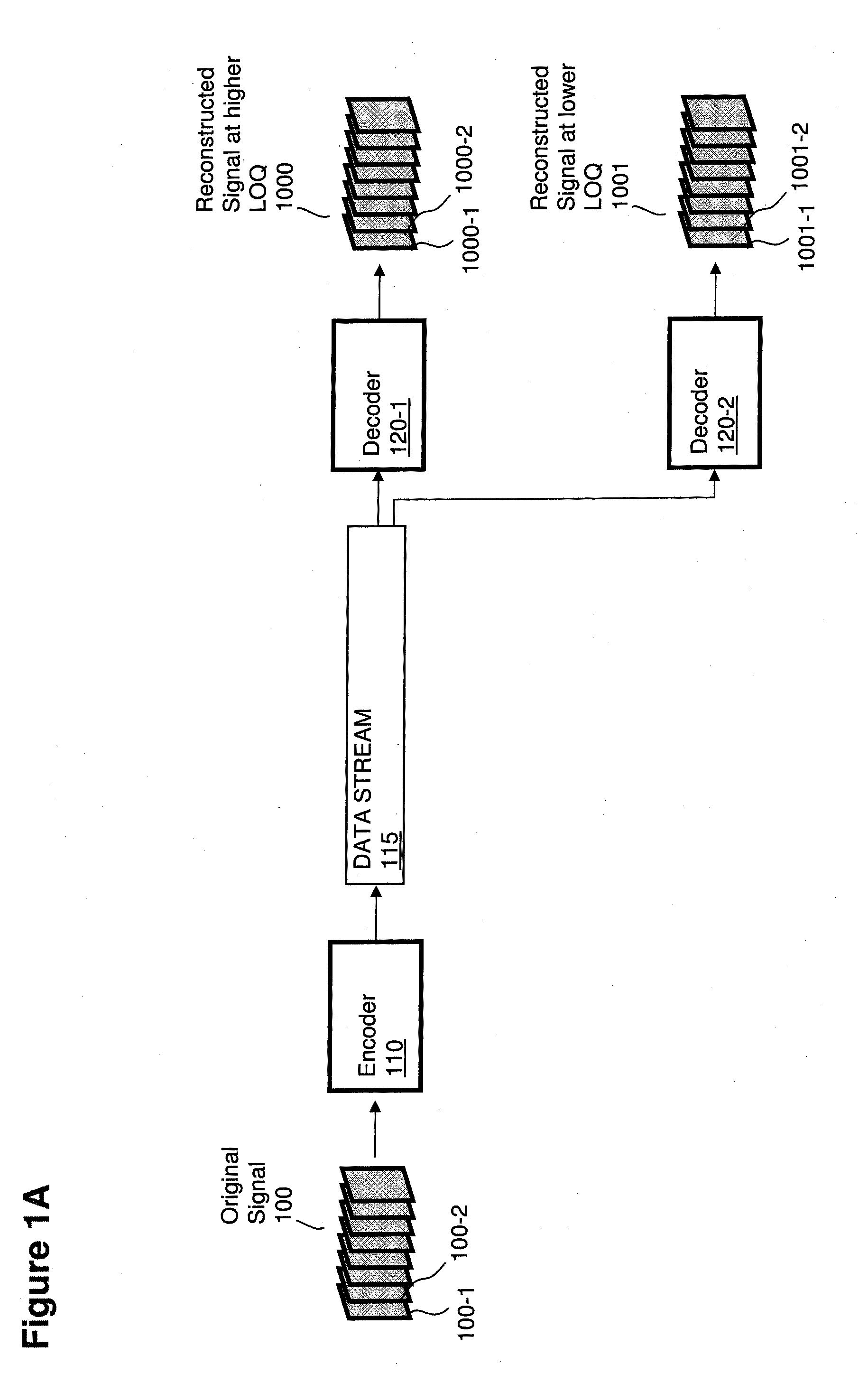
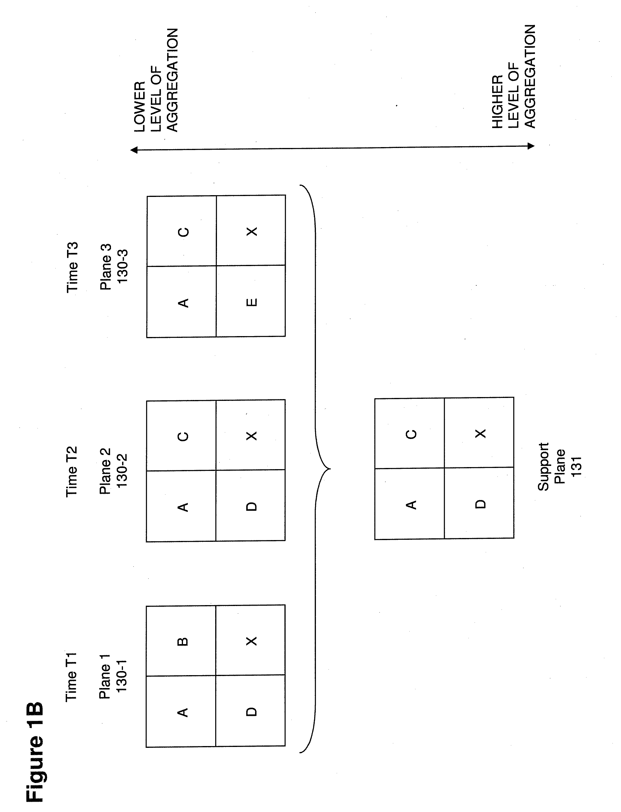
[0040]Instead of creating a “cascade of predictions” along images of a same sequence of images—like conventional methods—methods illustrated herein effectively blend the sequence of images into a same “common predictor” (which is—depending on the embodiment and/or on the purpose—either an image at a same resolution/level of quality as the original images or an image at a lower resolution/level of quality), and then produce sets of adjustment values such that a decoder can produce suitable renditions of the original images by combining said adjustment

Problems solved by technology

A drawback of conventional reference-based encoding techniques is that errors in a sample cumulate with errors in the following samples that are each reconstructed based on a precedent sample, creating visible artifacts after very few sequentially predicted samples as soon as lossy compression techniques are adopted.
The partition process is usually abrupt and prone to artifacts.
While compression efficiency is indeed achieved, it is also true that visible artifacts are introduced.
Many attempts to reduce the visibility of such artifacts have been implemented (e.g., de-blocking and de-ringing filters both on the encoder and the decoder side) although with disadvantages such as a reduced global perceived quality and an increased complexity.
This introduces artifacts in the time evolution of the signal (e.g., for significant movements the quality perceived often suffers from evident discontinuities along the edges of the GOP).
No encoding technology so far was designed so as to be optimally executed on massively parallel hardware, with computational performance that scales automatically based on the number of computing cores available (i.e., without having to adapt the code, or without even knowing in advance how many computing cores will be available).
Another aspect neglected in the known art, aside from few attempts, is the quality scalabil

Method used


Image

  • Encoding and decoding based on blending of sequences of samples along time
  • Encoding and decoding based on blending of sequences of samples along time
  • Encoding and decoding based on blending of sequences of samples along time

Examples


Embodiment Construction

[0074]Methods illustrated herein are suitable for any type of multi-dimensional signals, including without limitation sound signals, multichannel sound signals, pictures, two-dimensional images, video signals, multi-view video signals, 3D video signals, volumetric signals, volumetric video signals, medical imaging signals, signals with more than four dimensions, etc. For simplicity, along the description the illustrated embodiments usually adopt the use case of video sequences, i.e., a time-based signal consisting of a sequence of 2D images (commonly called “frames”, or “fields” in the case of interlaced video signals), with each element (in such non-limiting example case typically referred to as “pixel”) being characterized by a set of color settings in a suitable color space (e.g., YUV, RGB, HSV, etc.). Different color planes (e.g., the luminance-Y plane and the two chrominance—U and V—planes) are often encoded separately, and often with different resolutions (due to the lower sen...


PUM


Abstract

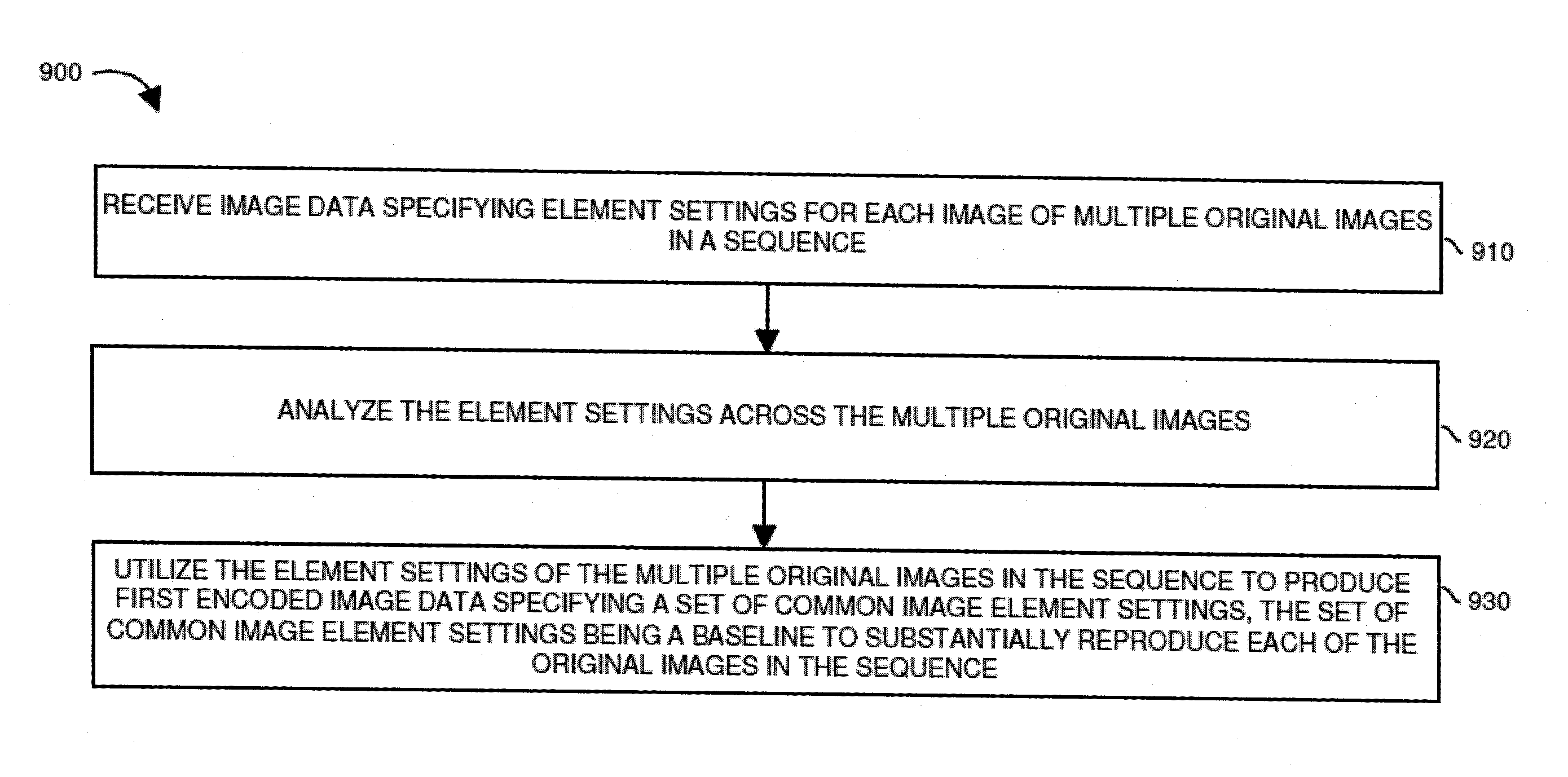
Computer processor hardware receives image data specifying element settings for each image of multiple original images in a sequence. The computer processor hardware analyzes the element settings across the multiple original images. The computer processor hardware then utilizes the element settings of the multiple original images in the sequence to produce first encoded image data specifying a set of common image element settings, the set of common image element settings being a baseline to substantially reproduce each of the original images in the sequence.

Description

RELATED APPLICATIONS[0001]This application is related and claims the benefit of U.S. Provisional Patent Application Ser. No. 61 / 646,797 entitled “SIGNAL ENCODING, DECODING AND RECONSTRUCTION OF TIME-BASED AND / OR MULTIDIMENSIONAL SIGNALS BASED ON MULTIDIMENSIONAL TIER-BASED INHERITANCE” (Attorney Docket No. VNO12-01p), filed on May 14, 2012, the entire teachings of which are incorporated herein by this reference.[0002]This application is related to and claims the benefit of U.S. Provisional Patent Application Ser. No. 61 / 647,426 entitled “ESTIMATION, ENCODING, DECODING AND USAGE OF MOTION INFORMATION IN MULTIDIMENSIONAL SIGNALS THROUGH MOTION ZONES, MOTION MATRIXES, WARP MAPS AND MOTION TRANSFORMS” (Attorney Docket No. VNO12-02p), filed on May 15, 2012, the entire teachings of which are incorporated herein by this reference.[0003]This application is also related to U.S. patent application Ser. No. 13 / 188,188 entitled “INHERITANCE IN A TIERED SIGNAL QUALITY HIERARCHY,” (Attorney Docke...

Claims


Application Information

Patent Timeline
IPC IPC(8): H04N7/36
CPCH04N19/00715H04N19/30G06T9/00G06T9/40H04N5/145H04N19/40H04N19/57H04N19/573
Inventor ROSSATO, LUCAMEARDI, GUIDO
Owner V NOVA INT LTD
Why Eureka
Try Eureka