Fuel-cell stack comprising a stack of cells and bipolar conductive plates

Inactive Publication Date: 2013-11-14
COMMISSARIAT A LENERGIE ATOMIQUE ET AUX ENERGIES ALTERNATIVES
View PDF5 Cites 2 Cited by
  • Summary
  • Abstract
  • Description
  • Claims
  • Application Information

AI Technical Summary

Benefits of technology

[0011]The present invention aims in particular to avoid these drawbacks of the prior

Problems solved by technology

One problem that arises in the case of starting a fuel-cell stack that is at a temperature below 0° C. is that the water produced by the electrochemical reaction risks freezing as long as that temperature is below the 0° C. threshold.
The fuel-cell stack then can no longer operate correctly, and risks b

Method used


Image

  • Fuel-cell stack comprising a stack of cells and bipolar conductive plates
  • Fuel-cell stack comprising a stack of cells and bipolar conductive plates
  • Fuel-cell stack comprising a stack of cells and bipolar conductive plates

Examples


Embodiment Construction

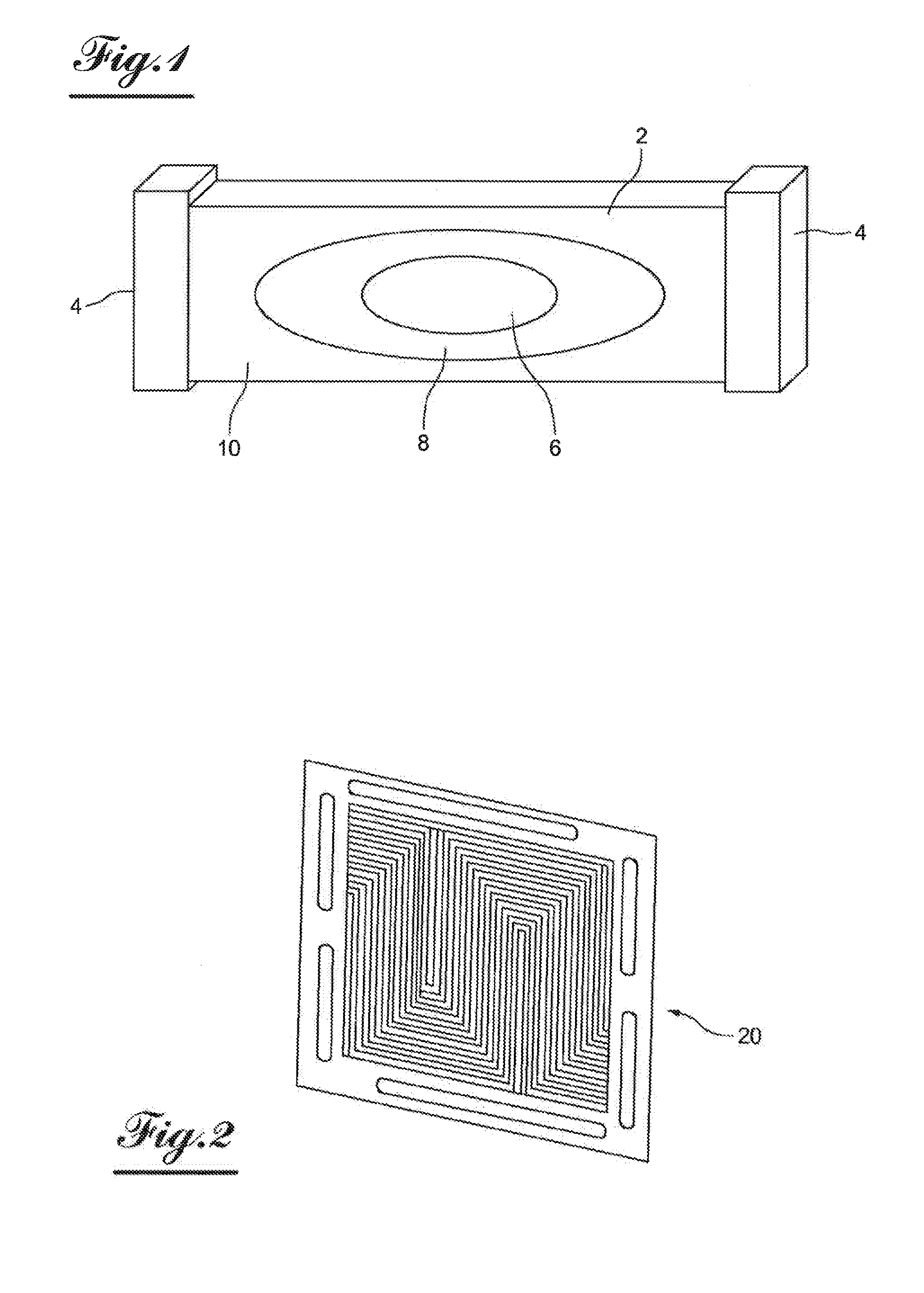
[0032]FIG. 1 shows a fuel-cell stack 1 comprising a series of cells 2 stacked with intermediate bipolar plates between said cells, bipolar plates each being passed through by a heat-transfer fluid of the cooling system that is managed by the management computer of the fuel-cell stack. The bipolar plates are identical and are supplied equally by the heat-transfer fluid.

[0033]The fuel-cell stack 1 includes, at each end, an end plate 4 that transmits the current to external connectors.

[0034]The fuel-cell stack 1 additionally includes an external circuit (not shown) for flowing heat-transfer fluid, comprising a flow pump and a fluid-air exchanger, to dissipate the calories taken from the cells 2 into the ambient air.

[0035]One can see that during the startup of the fuel-cell stack 1, different temperature zones are obtained, due in particular to the end plates 4 that make up heat masses that are slower to heat, and the heat exchangers of the cells with the ambient air, which are also hig...


PUM


Abstract

A fuel-cell stack including a stack of fuel cells with intermediate conductive bipolar plates. The bipolar plates include internal flow channels for flow of a heat-transfer fluid. The channels are connected to a circuit of a cooling system. Only some of the bipolar plates include internal flow channels that are temporarily or permanently not in service.

Description

FIELD OF THE INVENTION[0001]The present invention relates to a fuel-cell stack comprising a cooling system using a heat-transfer fluid, and also relates to a generator and a motor vehicle equipped with this type of fuel-cell stack.BACKGROUND[0002]Fuel-cell stacks are developed in particular to equip vehicles to replace heat engines, so as to improve the energy output and reduce polluting gas emissions.[0003]Fuel-cell stacks generally include a stack of elementary cells comprising two electrodes separated by an electrolyte, connected to each other by conductive bipolar plates including internal ducts to provide said electrodes with the products necessary for the reaction, and channels for flow of a heat-transfer fluid.[0004]The electrochemical reactions that occur in contact with the electrodes generate electrical current and produce water, while giving off heat energy that heats the various components.[0005]To operate correctly, the fuel-cell stacks must be at a certain temperature ...

Claims


Application Information

Patent Timeline
IPC IPC(8): H01M8/04
CPCH01M8/04074B60L1/02B60L3/0053B60L2240/36H01M8/0267H01M8/04029B60L50/72B60L58/34B60L58/33Y02T90/40Y02E60/50H01M8/2483H01M8/0263H01M8/241H01M8/0258
Inventor GLIPA, XAVIERRANJARD, JEAN-FRANCOISPINTON, ERICPOIROT CROUVEZIER, JEAN-PHILIPPEBEGOT, SYLVIEHAREL, FABIENLE CANUT, JEAN-MARC
Owner COMMISSARIAT A LENERGIE ATOMIQUE ET AUX ENERGIES ALTERNATIVES
Why Eureka
Try Eureka