
Method and Apparatus for Automated Configuration of a Monitoring Function of a Machine Tool

a technology of automatic configuration and machine tools, applied in the direction of program control, total factory control, instruments, etc., can solve the problems of a large quantity of scrape components, a large amount of scrape parts, and the probability of a tool breaking for a strong worn out tool increasing

Active Publication Date: 2013-11-14
MARPOSS MONITORING SOLUTIONS GMBH
View PDF12 Cites 42 Cited by
  • Summary
  • Abstract
  • Description
  • Claims
  • Application Information

AI Technical Summary

Benefits of technology

The invention is a method for automatically adjusting a monitoring function in a machining process on a machine tool. This method ensures that human error has minimal impact on the setup process of the monitoring function or the monitoring system. The method analyzes processing steps and determines the function of the monitoring system for each step, ensuring optimal synchronization of the machining process and the monitoring function. Based on these targets, the monitoring system optimizes its configuration for the machining process on the machine tool.

Problems solved by technology

These opposing objectives can often only be fulfilled by using a large degree of automation.
However, an automated production line can lead to a large quantity of scrape components in a short period if an error occurs, if the error is not detected or is not detected in time.
Moreover, the probability for a breakage of a tool increases for a strongly worn out tool.
High reject rates can occur if a missing or a broken tool is not recognized or not recognized in time.
In the worst case, defective work pieces or components are built into final products which can lead to large damages at the customer side.
The discussed difficulty also applies if incorrect work pieces are not detected or not detected in time and are thus processed by the production line.
These work pieces have to be finally rejected at the end of the processing or are erroneously built in a final product.
However, the PLC of the machine tool does not know (i.e., is not aware of) a second portion of the control commands of the monitoring system.
This results in a significant adaptation effort for the respective control program, and is very time consuming in particular for long control programs, or even not possible.
As a result, these difficulties often lead to the problem that the operating staff does not at all or does not sufficiently adapt the monitoring system to the machining process to be processed.
Thus, the monitoring system is often used in a wrong mode and / or with a reduced functionality.

Method used


Image

  • Method and Apparatus for Automated Configuration of a Monitoring Function of a Machine Tool
  • Method and Apparatus for Automated Configuration of a Monitoring Function of a Machine Tool
  • Method and Apparatus for Automated Configuration of a Monitoring Function of a Machine Tool

Examples


Embodiment Construction

[0081]In the following, presently preferred implementation examples of the inventive method and the inventive apparatus for an automated provision of a monitoring function for a machining process executed by a machine tool are explained in detail. These exemplified explanations are described in the context of a machine tool with a spindle. However, the described method can also be used in or with respect to any type of machine tool.

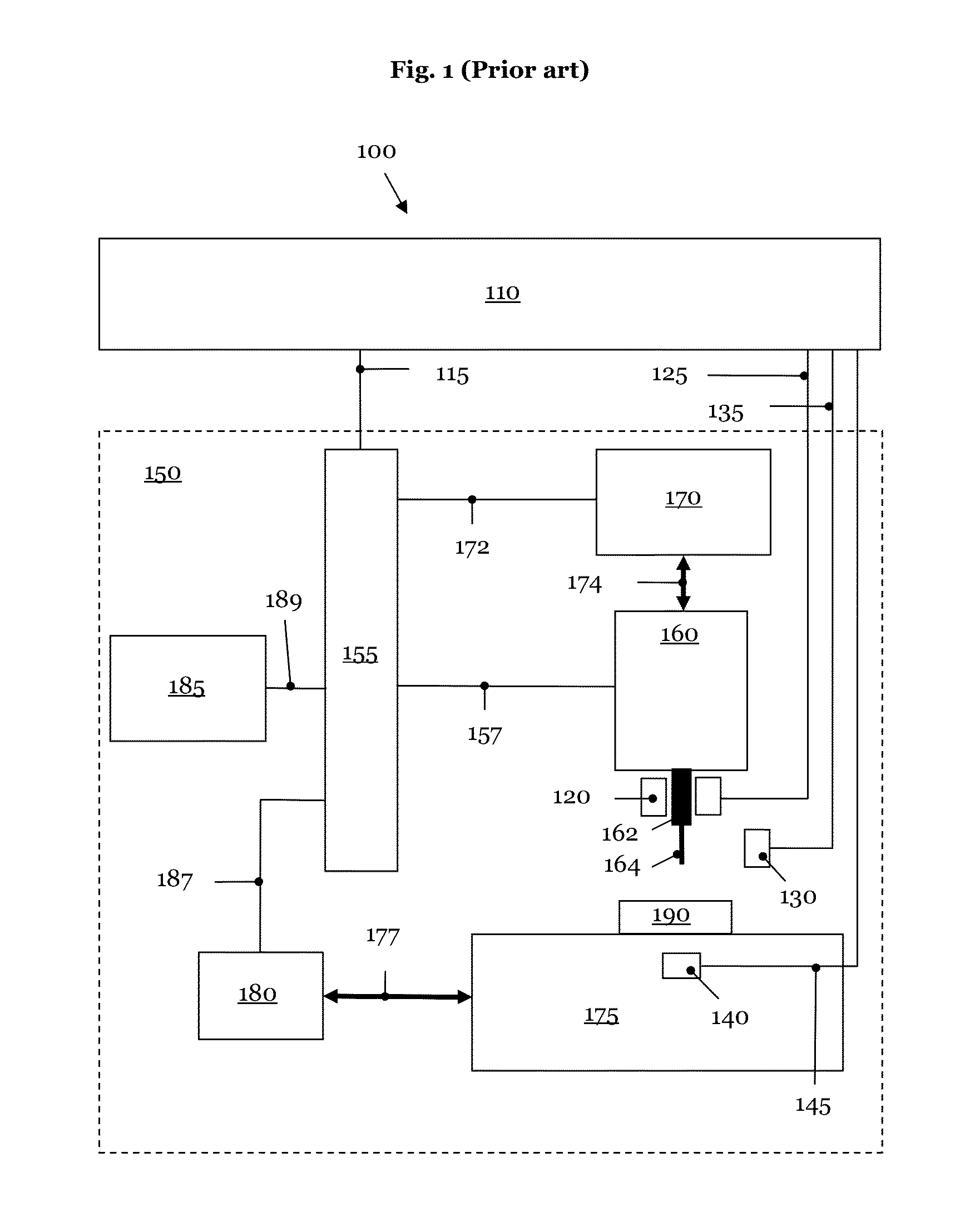
[0082]FIG. 1 shows a combination 100 of a monitoring system 110 and some important components of a machine tool 150. The machine tool 150 has a main drive 160 with a spindle 162. The tool mount of the spindle holds the tool 164. In the example represented in FIG. 1, the spindle 162 holds a cutter 164. However, the tool 164 of the machine tool 150 is not restricted to the application of a cutter 164. Rather, the tool mount of the spindle 162 can pick up all kinds of rotating tools 164, as for example drills, broaching tools, or thread drills (not shown in ...


PUM


Abstract

System and method for automated provision of a monitoring function for a machining process which is to be executed by a machine tool. A computer-aided manufacturing (CAM) program of the machining process is automatically analyzed by means of a postprocessor in order to determine processing steps to be monitored. At least one monitoring instruction may be automatically inserted into a control program of the machine tool by the postprocessor, wherein the control program is executed during the machining process.

Description

PRIORITY CLAIM[0001]This application claims benefit of priority of German application no. 102012207916.5 titled “Method and Apparatus for an Automated Configuration of a Monitoring Function of a Machine Tool”, filed May 11, 2012, and whose inventors are Dirk Lange, Dirk Euhus, and Frank August Joachim Bonas.INCORPORATED BY REFERENCE[0002]German application no. 102012207916.5 titled “Method and Apparatus for an Automated Configuration of a Monitoring Function of a Machine Tool”, filed May 11, 2012, and whose inventors are Dirk Lange, Dirk Euhus, and Frank August Joachim Bonas, is hereby incorporated by reference in its entirety as though fully and completely set forth herein.TECHNICAL FIELD[0003]The present invention refers to a method and an apparatus for an automated configuration of a monitoring function of a machine tool.DESCRIPTION OF THE RELATED ART[0004]Today manufacturing plants have to fulfill high requirements with respect to cost effectiveness and productivity. On the othe...

Claims


Application Information

Patent Timeline
IPC IPC(8): G05B19/18
CPCG05B19/18G05B19/4097G05B2219/23031Y02P90/02
Inventor LANGE, DIRKEUHUS, DIRKBONAS, FRANK AUGUST JOACHIM
Owner MARPOSS MONITORING SOLUTIONS GMBH
Learn More