Grain retainer construction for air bag inflator

Active Publication Date: 2013-11-21
ARC AUTOMOTIVE
View PDF1 Cites 0 Cited by
  • Summary
  • Abstract
  • Description
  • Claims
  • Application Information

AI Technical Summary

Benefits of technology

The grain retainer construction in this patent uses claws or beams to support propellant grains in a pressure vessel. These claws or beams are bent inward during assembly to create a gap between the vessel wall and the grains. This gap helps prevent heat transfer and reduces the pressure in the vessel, which increases safety in the air bag inflator.

Problems solved by technology

In such known constructions, the propellant grains mounted in the pressure vessel may be subject to auto ignition if the external heat on the pressure vessel exceeds a certain value.

Method used


Image

  • Grain retainer construction for air bag inflator
  • Grain retainer construction for air bag inflator
  • Grain retainer construction for air bag inflator

Examples


Embodiment Construction

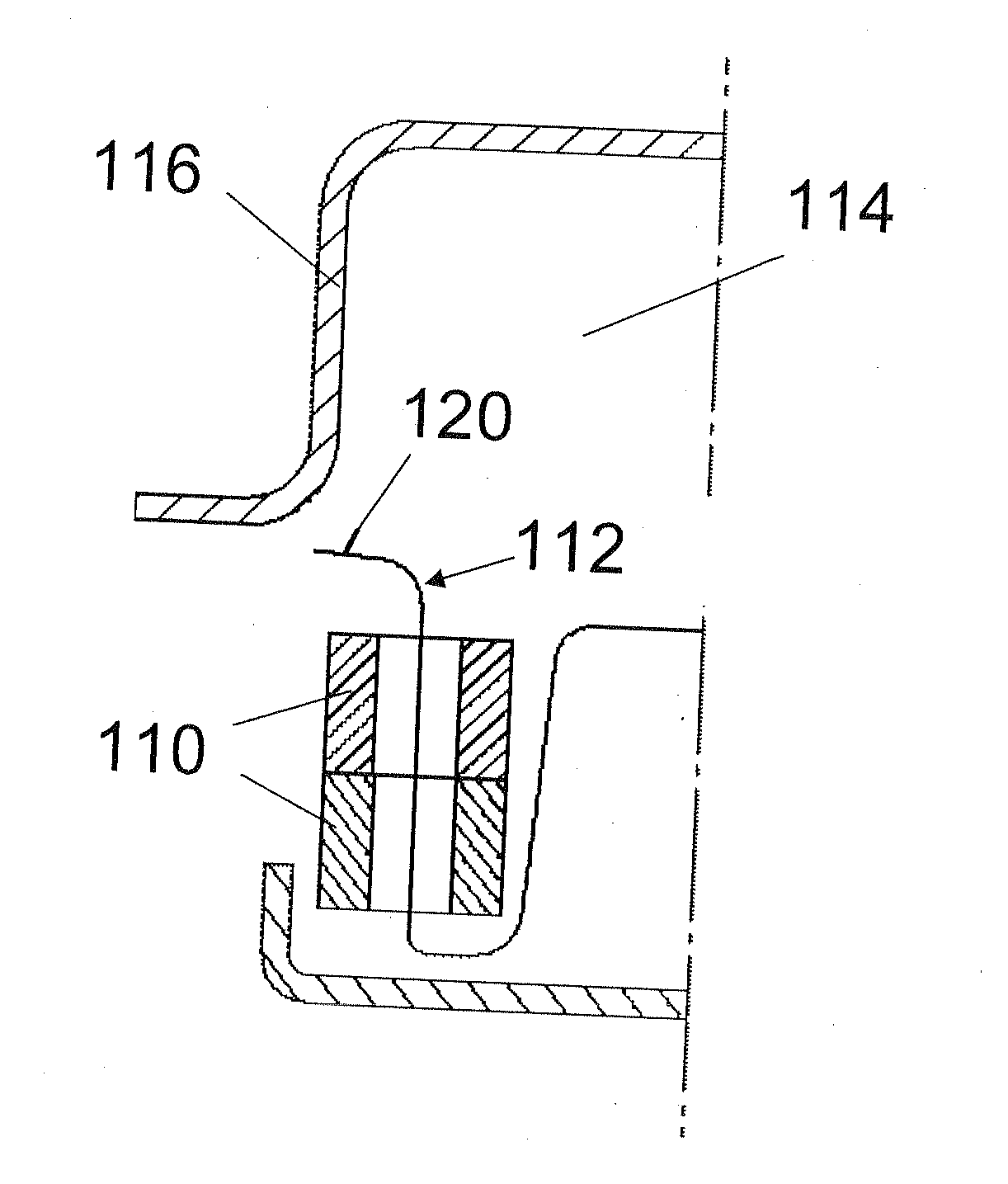
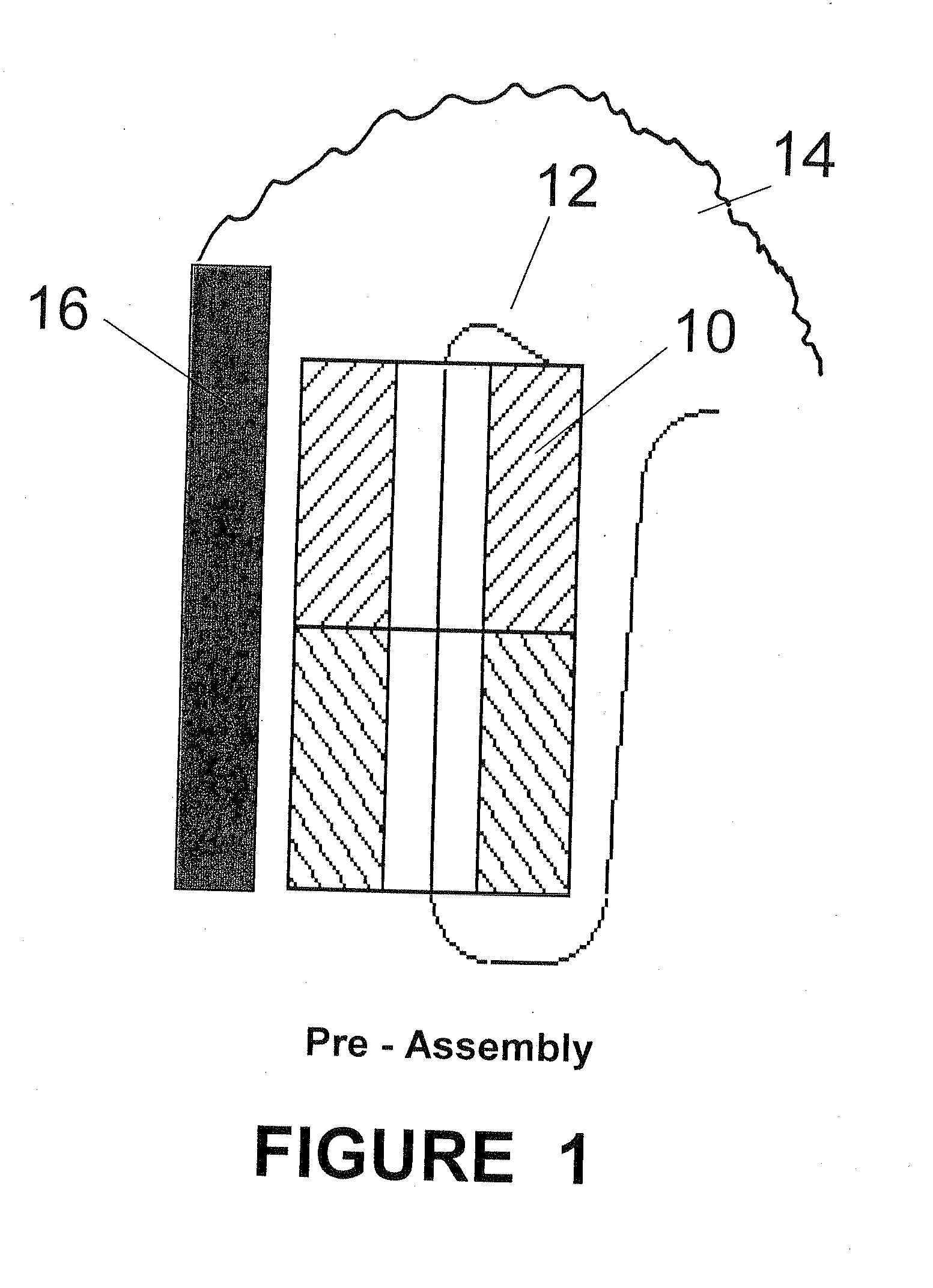
[0014]As shown in FIG. 1, one ore more propellant grains 10 are mounted on a cantilevered finger or beam 12 which extends upwardly in the combustion chamber 14 enclosed by the pressure vessel wall 16.

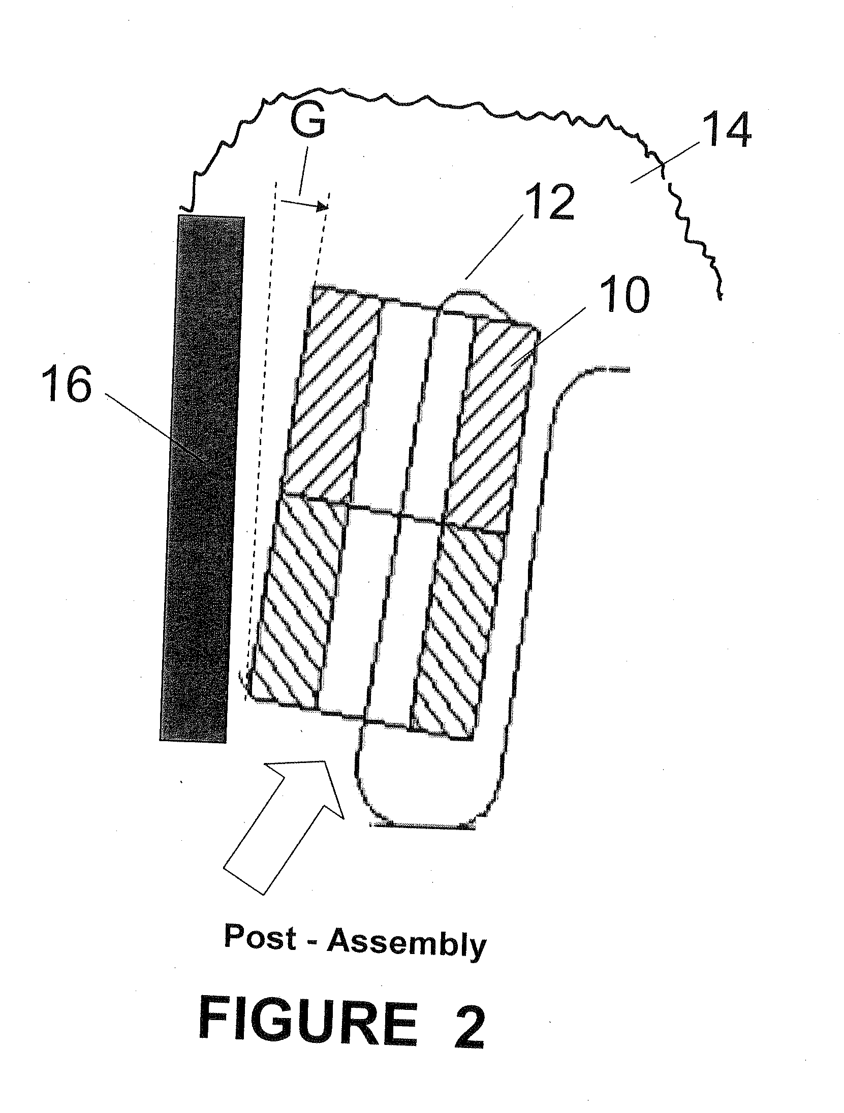
[0015]During the assembly of the pressure vessel, the air gap between the propellant grains 10 and the adjacent pressure vessel wall 16 is increased to reduce heat transfer therebetween by deforming the supporting finger or beam laterally inwardly as shown in FIG. 2. The finger or beam 12 may be deformed inwardly in any suitable manner, such as by manual deformation thereof or by contact of the finger or beam, or the propellant grains mounted thereon with the pressure vessel wall 16 or other contact surfaces in the pressure vessel. The increase in the air gap G between the propellant grains and the pressure vessel wall 16 reduces heat transfer therebetween which in turn reduces operating pressures in the pressure vessel by reducing the temperature and burn rate of the gas generant to in...


PUM

PropertyMeasurementUnit
Electrical resistanceaaaaaaaaaa
Flexibilityaaaaaaaaaa

Abstract

A propellant grain retainer for an air bag inflator having a pressure vessel. A cantilevered finger is mounted in the pressure vessel and a propellant grain is mounted thereon. Upon assembly of the pressure vessel, the finger is deformed inwardly away from an adjacent wall of the pressure vessel to increase the air gap between the pressure vessel wall and the propellant grain to reduce heat transfer therebetween and increase the safety of the inflator.

Description

BACKGROUND OF THE INVENTION[0001]1. Field of the Invention[0002]The present invention relates to a grain retainer construction for an air bag inflator and, more particularly, to such a construction that creates an increased gap between the propellant and the surrounding pressure vessel so that there is reduced heat transfer between them.[0003]2. Description of the Background Art[0004]To secure propellant grains in place in a pressure vessel of an air bag inflator, it is a common practice to utilize “fingers” or elongated retainers which extend through holes in the grains. When the grains are mounted on the retainers, they are normally in contact with or closely adjacent to the wall of the pressure vessel where they are subject to significant heat transfer from the pressure vessel wall when the pressure vessel is exposed to external heat, such as from welding or being exposed to external heat for any other reason. In such known constructions, the propellant grains mounted in the pres...

Claims


Application Information

Patent Timeline
IPC IPC(8): B65D81/38B23P17/04
CPCB60R21/2644Y10T29/49826
Inventor OVERTON, DOUGLAS EARLROSE, JAMES MICHAEL
Owner ARC AUTOMOTIVE
Why Eureka
Try Eureka