Fuel injection valve

a technology of fuel injection valve and fuel injection valve, which is applied in the direction of magnets, machines/engines, magnets, etc., can solve the problems of over-all negative functional properties, constructions are bound up with substantial additional costs in their manufacture, and achieve compact design

Active Publication Date: 2013-11-21
ROBERT BOSCH GMBH
View PDF4 Cites 5 Cited by
  • Summary
  • Abstract
  • Description
  • Claims
  • Application Information

AI Technical Summary

Benefits of technology

[0007]The fuel injector according to the present invention has the advantage of a particularly compact design. The valve has an extremely small outer diameter such as persons skilled in the art in the area of manifold injectors for internal combustion engines hitherto thought impossible to manufacture at the highest functionality. These very small dimensions make it possible to design the installation of the fuel injector in a much more flexible manner than was previously conceivable. Due to the modularly constructed valve, the fuel injectors according to the present invention may thus be installed in a very compatible manner in the greatest variety of receiving bores of the different vehicle manufacturers including numerous “extended tip” variants, that is, fuel injector variants of varying lengths, without changing the valve needle length or the injector sleeve length. For this purpose, the sealing ring situated on the outer magnetic circuit component and sealing against the wall of the receiving bore on the induction pipe is readily displaceable.

Problems solved by technology

The positive aspect of a very high electrical resistance arising in this connection, however, is countered by an extremely high magnetic resistance, which is reflected in a substantial loss of force and thus determines the overall negative functional properties.
Such constructions, however, are bound up with substantial additional costs in their manufacture.

Method used


Image

  • Fuel injection valve
  • Fuel injection valve
  • Fuel injection valve

Examples


Embodiment Construction

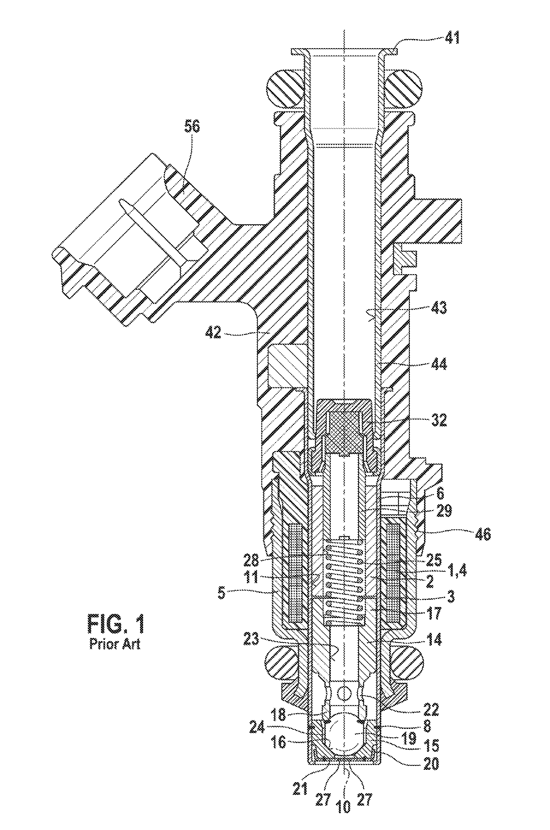
[0014]For a better understanding of the present invention, FIG. 1 shows in exemplary fashion an electromagnetically operable valve in the form of a fuel injector for fuel-injection systems of mixture-compressing, externally ignited internal combustion engines according to the related art.

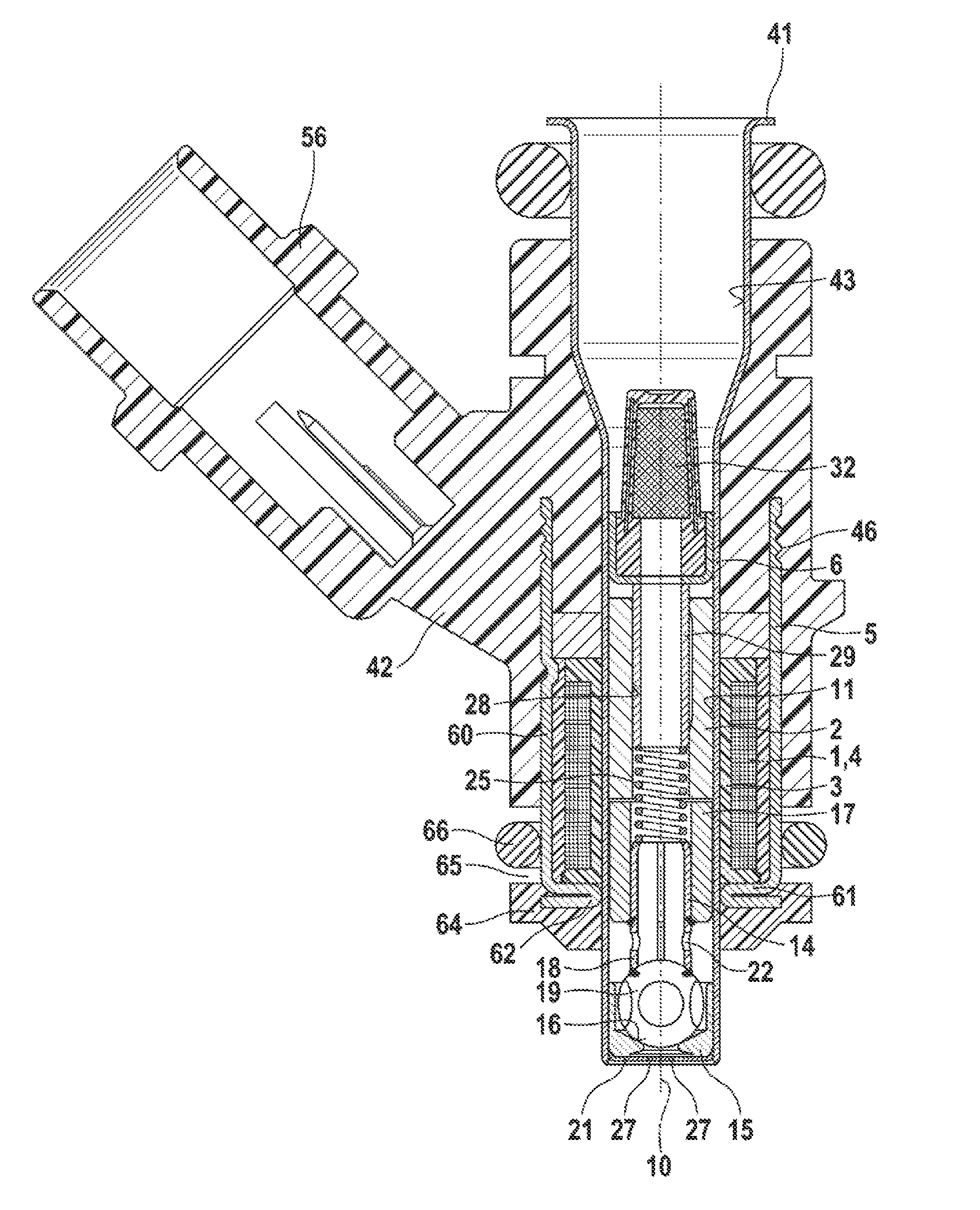
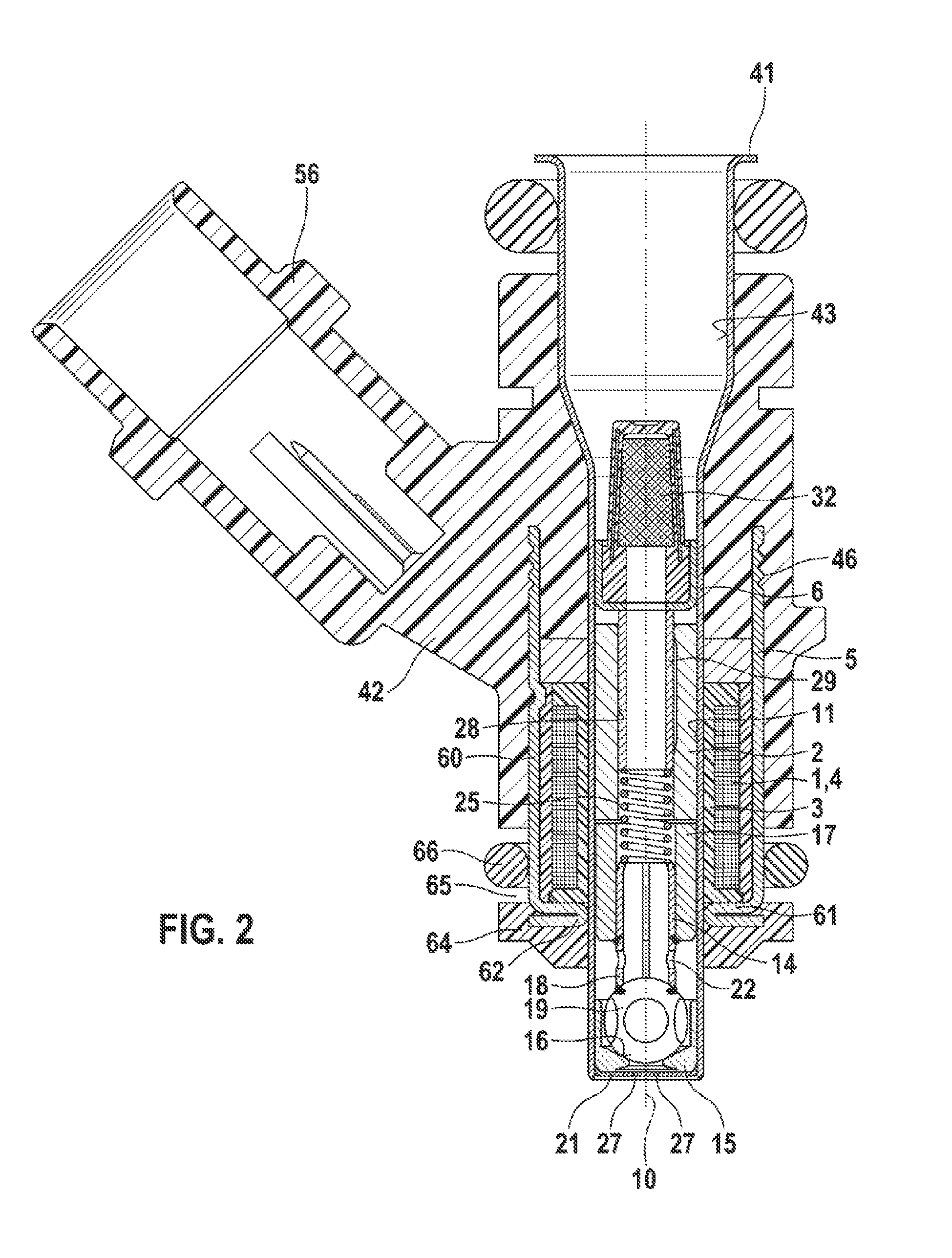
[0015]The valve has a largely tubular core 2, which is surrounded by a solenoid coil 1 and serves as inner pole and partially as fuel passage. In the circumferential direction, solenoid coil 1 is completely surrounded by an outer, sleeve-shaped and stepped, e.g., ferromagnetic valve jacket 5, which constitutes an outer magnetic circuit component acting as external pole. Solenoid coil 1, core 2 and valve jacket 5 together form an electrically excitable actuating element.

[0016]While solenoid coil 1 having a winding 4 and being embedded in a coil shell 3 encloses a valve sleeve 6 from outside, core 2 is inserted into an inner opening 11 of valve sleeve 6 extending concentrically with respect to a longi...


PUM


Abstract

A fuel injector for fuel-injection systems of internal combustion engines includes an electromagnetic actuating element having a solenoid coil, a fixed core, an outer magnetic circuit component, and a movable armature for actuating a valve-closure element, which cooperates with a valve-seat surface provided on a valve-seat element. The injector is characterized by its extremely small outer dimensions. The flexibility in the installation of fuel injectors of varying valve lengths, which is made possible very simply due to the special modular design, is significantly increased in this manner. An optimized dimensioning of the electromagnetic circuit allows for a DFR (dynamic flow range) greater than 17, the DFR being defined as the quotient of qmax/qmin.

Description

BACKGROUND OF THE INVENTION[0001]1. Field of the Invention[0002]The present invention relates to a fuel injector.[0003]2. Description of the Related Art[0004]A fuel injector, which includes an electromagnetic actuation element having a solenoid coil, an internal pole and an external magnetic circuit component as well as a movable valve-closure element, which cooperates with a valve seat assigned to a valve-seat body, is already known from published German patent application document DE 38 25 134 A1. The fuel injector is surrounded by a plastic extrusion coat, the plastic extrusion coat extending primarily in the axial direction so as to surround the connecting piece that acts as the inner pole as well as the solenoid coil. At least in the region surrounding the solenoid coil, ferromagnetic filler materials conducting magnetic lines of force are embedded in the plastic coating. In this respect, the filler materials surround the solenoid coil in the circumferential direction. The fill...

Claims


Application Information

Patent Timeline
Patent Type & Authority Applications(United States)
IPC IPC(8): F02M51/06
CPCF02M51/0614F02M51/0682F02M2200/08F02M2200/9061H01F7/1607
Inventor GRANGER, JUERGENMAIER, MARTINMIZOBE, TAKUYARIEG, BERNDSOHM, VOLKERLANDER, JUERGEN
Owner ROBERT BOSCH GMBH
Why Eureka
Try Eureka