
Thin display device

a display device and thin technology, applied in the field of thin display devices, can solve the problems of device damage, liquid crystal display devices and other display devices (e.g., plasma display devices), tend to deteriorate in mechanical strength as a display, etc., and achieve the effect of preventing the damage of the display panel and effective protection of the thin display devi

Inactive Publication Date: 2013-11-21
PANASONIC INTELLECTUAL PROPERTY MANAGEMENT CO LTD
View PDF12 Cites 13 Cited by
  • Summary
  • Abstract
  • Description
  • Claims
  • Application Information

AI Technical Summary

Benefits of technology

This patent aims to prevent thin display devices from getting damaged during transportation. It achieves this by effectively protecting the device from a mechanical impact, which could lead to damage to the display panel. This results in a more robust and reliable transportation experience for thin display devices.

Problems solved by technology

Since being made much thinner compared with conventional devices and adapting the narrow frame design, the liquid crystal display devices and other display devices (e.g., plasma display devices) tend to deteriorate in mechanical strength as a display.
This causes a problem that the device is damaged by a mechanical impact during transportation.

Method used


Image

  • Thin display device
  • Thin display device
  • Thin display device

Examples


Embodiment Construction

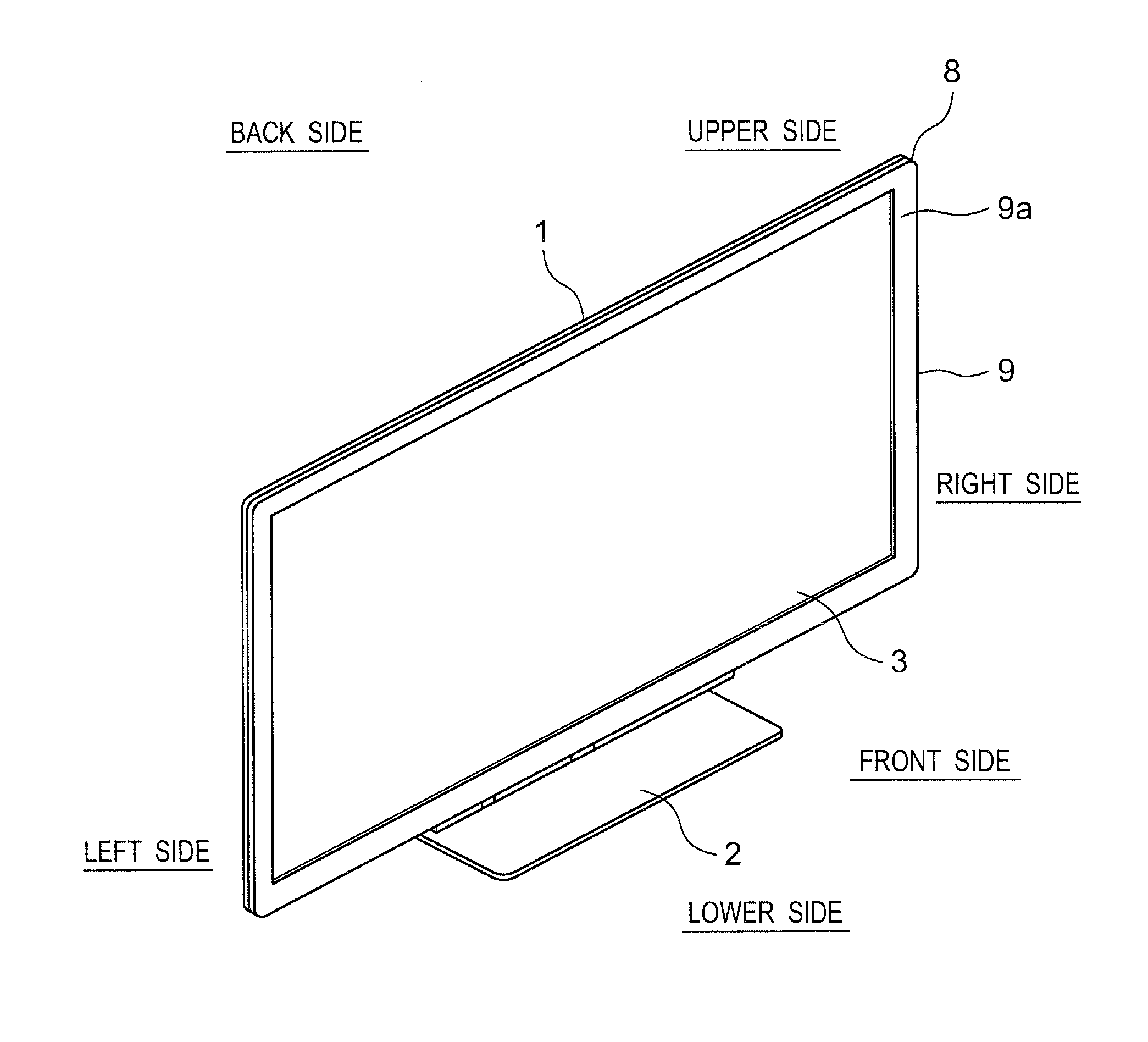
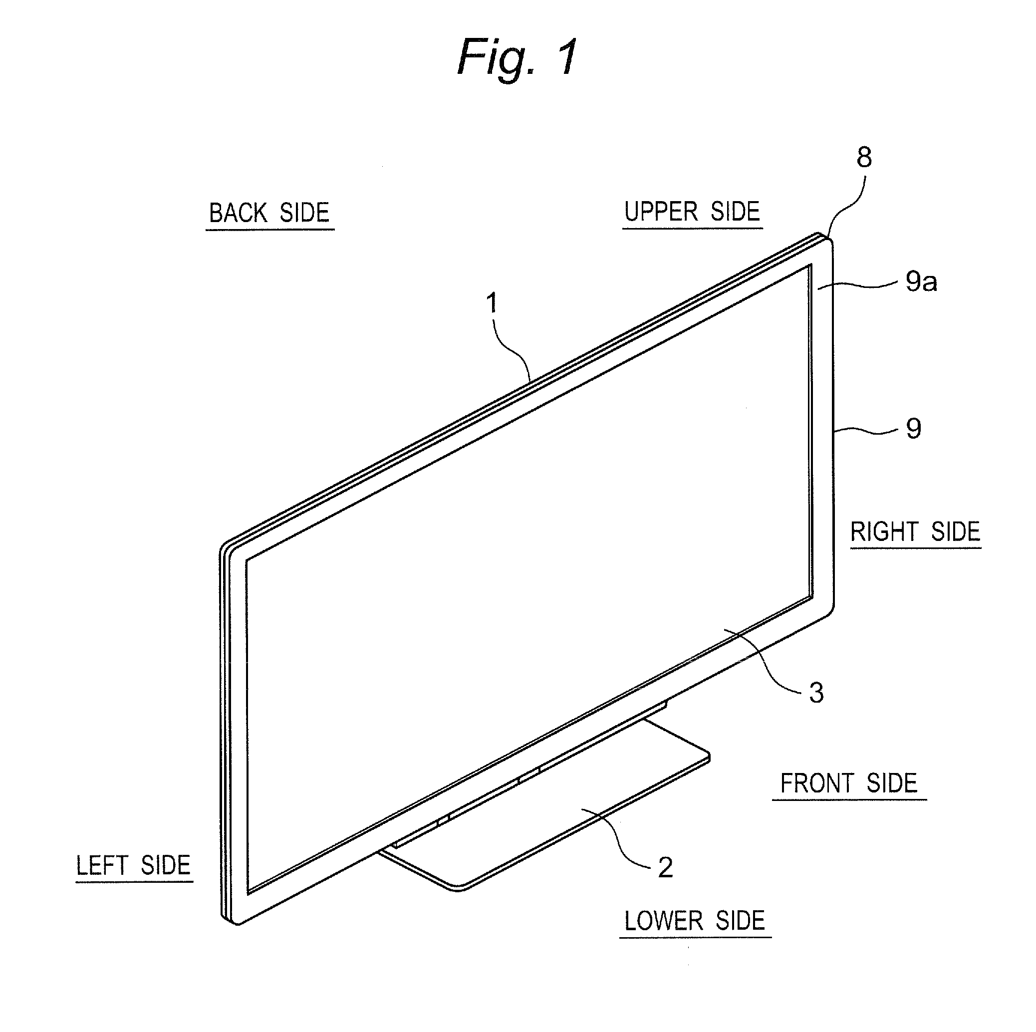
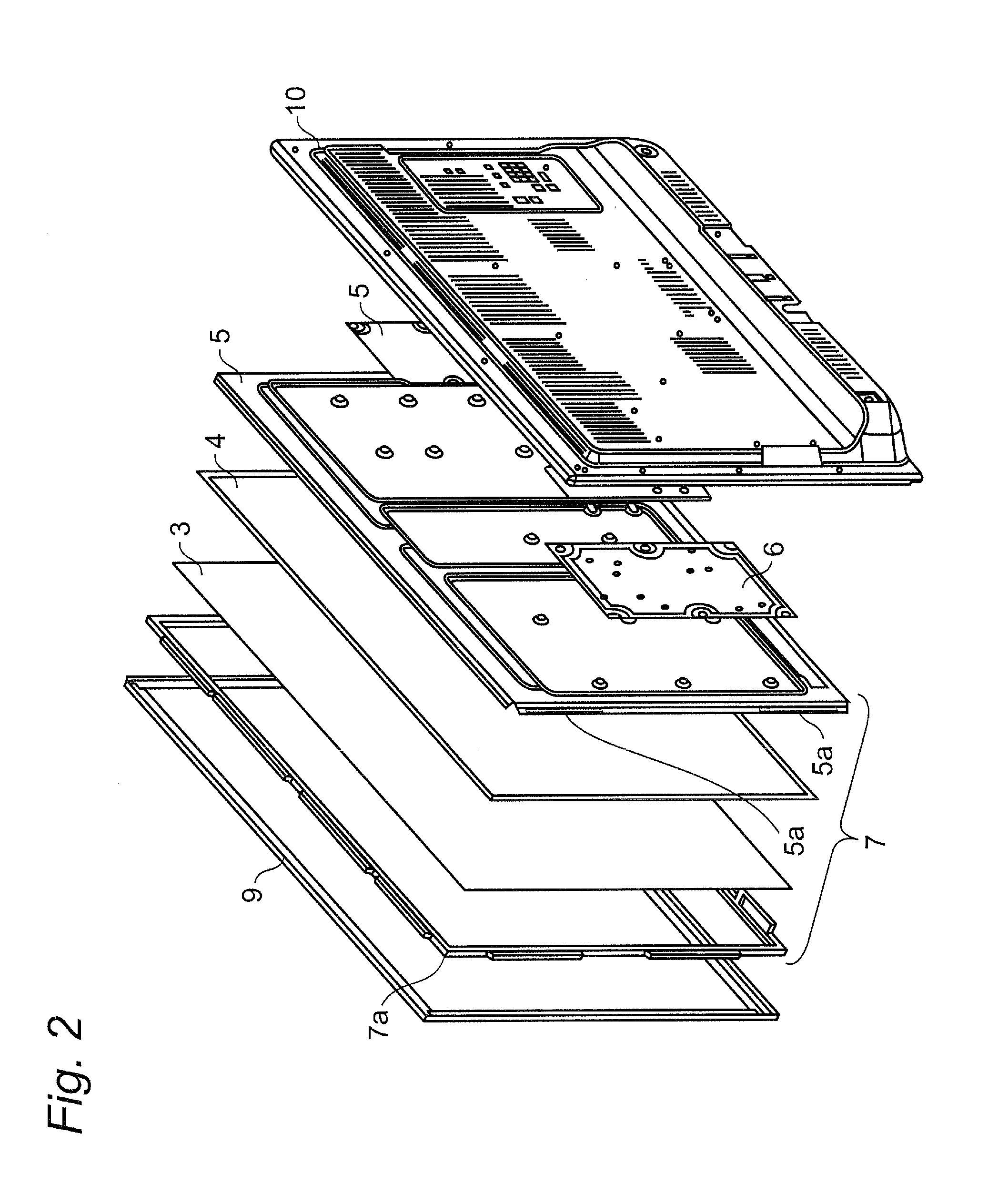
[0021]A thin display device according to an embodiment of the present disclosure will be described with reference to the drawings by taking an example of a display module used for a liquid crystal display device. Excessively detailed description will be omitted if applicable. For example, detailed description of an already known matter and redundant description of essentially the same configurations will be omitted if applicable. This is for preventing the following description from being unnecessarily redundant, and for facilitating understanding of those who skilled in the art. The present inventors provide the accompanying drawings and the following description for those skilled in the art to fully understand the present disclosure and do not intend to limit the subject matter defined in claims by the attached drawings and the following description.

[0022]FIG. 1 shows outward appearance of a liquid crystal display device, which is a completed product, in the embodiment of the pres...


PUM


Abstract

A thin display device includes a display unit and an exterior case. The exterior case accommodates the display unit therein. When accommodated in a packing case, the exterior case 8 is held by shock-absorbing members at upper and lower corner regions. A back cabinet of the exterior case is mounted on the display unit so as to cover a back side of the display unit. The display unit includes bead portions for reinforcement on peripheries of the upper and lower corner regions held by the shock-absorbing members. The display unit also includes a plurality of screw-fitting portions on the bead portions. The back cabinet is threadedly mounted on the screw-fitting portions. It is possible to prevent the thin display device from being damaged by a mechanical impact during transportation.

Description

CROSS-REFERENCE TO RELATED APPLICATIONS[0001]This is a continuation application of International Application No. PCT / JP2013 / 000102, with an international filing date of Jan. 11, 2013, which claims priority of Japanese Patent Application No.: 2012-055549 filed on Mar. 13, 2012, the content of which is incorporated herein by reference.BACKGROUND[0002]1. Technical Field[0003]The present disclosure relates to a thin display device such as a liquid crystal display device and a plasma display device used for a television receiver and a monitor device or the like.[0004]2. Description of Related Art[0005]Needs for liquid crystal display devices has been growing as professional-use as well as residential-use flat-type video display unit.[0006]Generally, the liquid crystal display device is configured in such a manner that a backlight device as a surface light source is disposed on a back side of a flat liquid crystal display panel to configure a display module, and this display module is acc...

Claims


Application Information

Patent Timeline
Patent Type & Authority Applications(United States)
IPC IPC(8): H05K5/02H05K5/00
CPCH05K5/0217H05K5/0017H04N5/64B65D81/055B65D81/057B65D2585/6837G06F1/1601G06F2200/1612G02F1/133314
Inventor SASAKI, HISANORIYAMANO, YOSHIKAZUOGURA, MOTONARI
Owner PANASONIC INTELLECTUAL PROPERTY MANAGEMENT CO LTD
Learn More