Switching power supply device

Active Publication Date: 2013-11-21
FUJI ELECTRIC CO LTD
View PDF2 Cites 7 Cited by
  • Summary
  • Abstract
  • Description
  • Claims
  • Application Information

AI Technical Summary

Benefits of technology

[0023]In some embodiments, in the switching power supply device having the construction described above, consideration is directed to a gradient of the inductor current to detect the timing of zero current, or the critical point, flowing in the inductor. Consequently, turning ON of the switching element can be carried out at the timing of lowest voltage on the switching element Q irrespective of input voltage variation. Therefore, the switching element does not operate in a continuous mode even when the input voltage Vi is high. Because the switching element is surely turned OFF at the timing of the lowest voltage, or at the valley of voltage oscillation, unde

Problems solved by technology

Therefore, the switching efficiency dete

Method used


Image

  • Switching power supply device
  • Switching power supply device
  • Switching power supply device

Examples


Example

[0031]The following describes a switching power supply device according to an embodiment of the present invention with reference to the accompanying drawings.

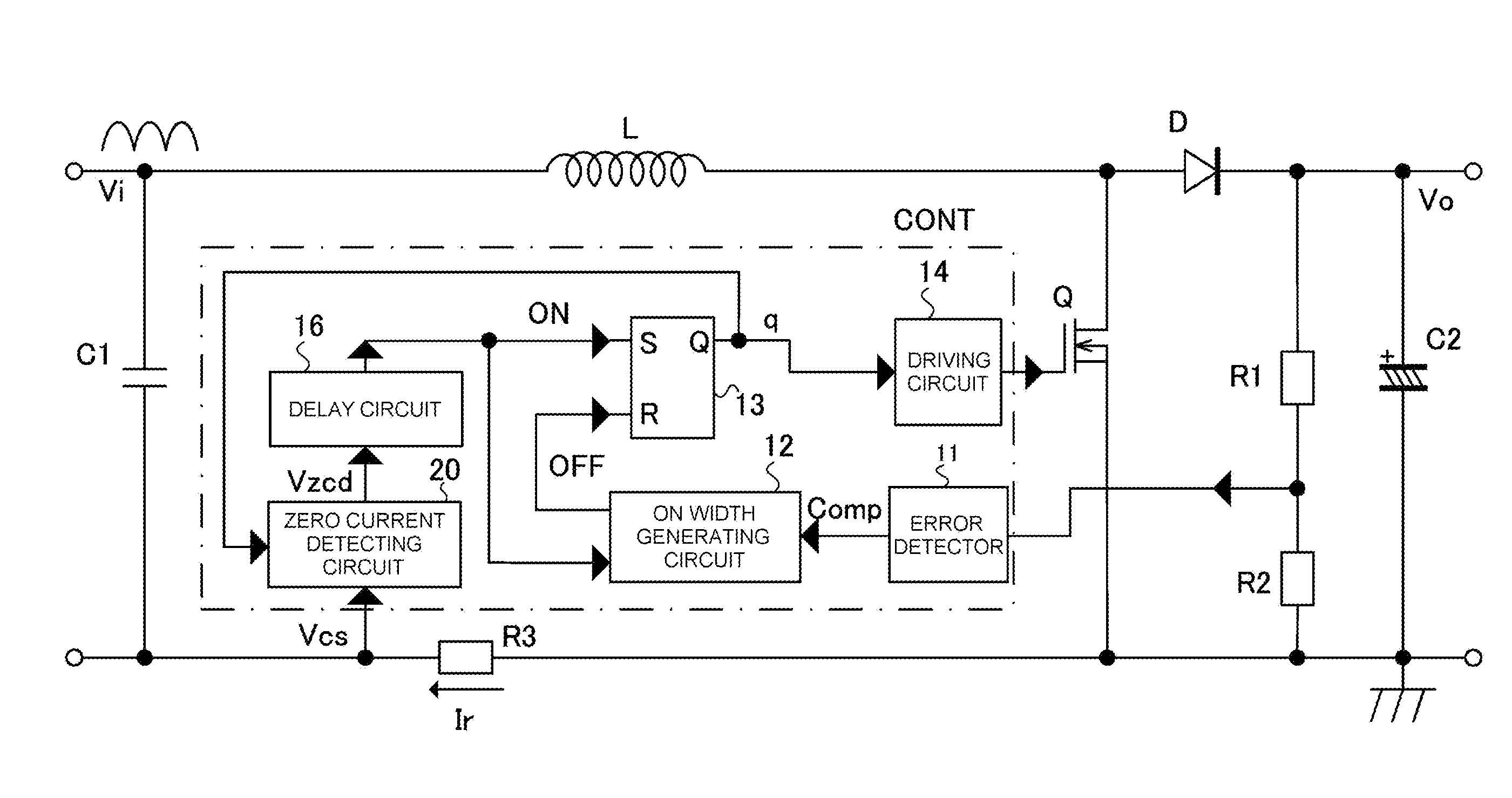
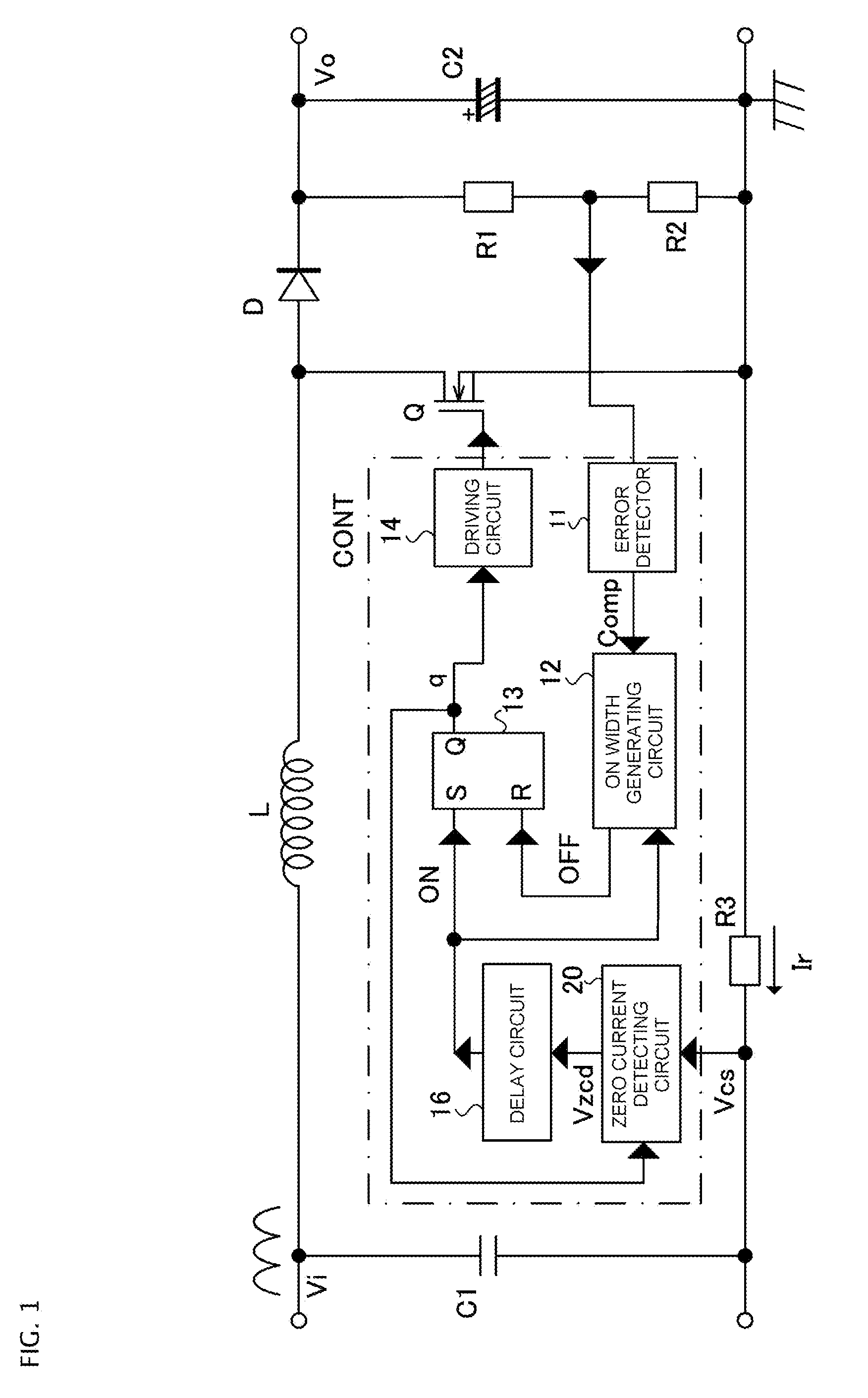
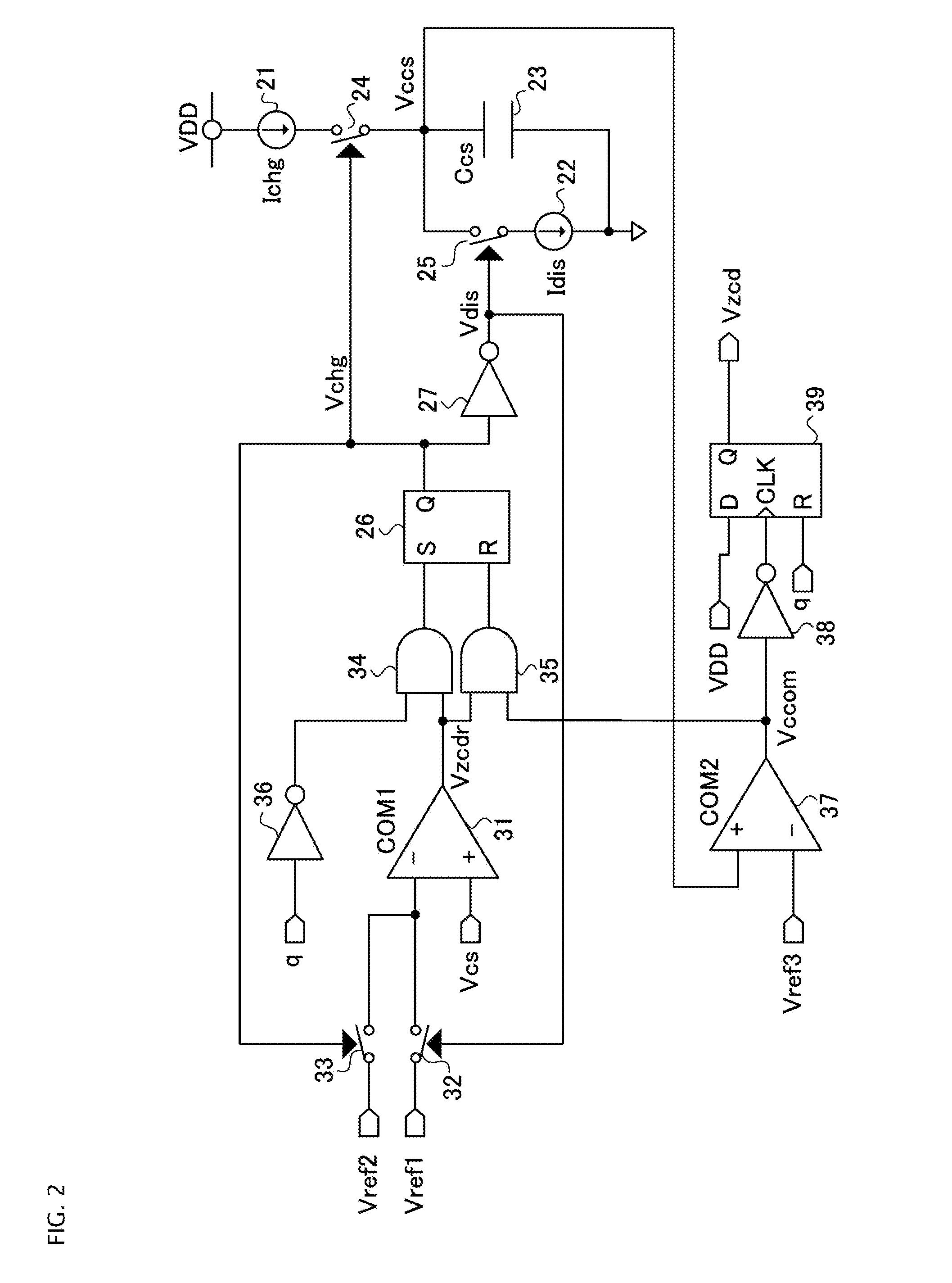
[0032]FIG. 1 shows a schematic construction of a switching power supply device 1, a power factor correction converter, of a step-up chopper type of the embodiment; and FIG. 2 shows a schematic construction of a zero current detecting circuit 20 in the switching power supply device 1 shown in FIG. 1. In FIG. 1, the same parts as those in the switching power supply device of FIG. 4 are given the same symbols. The input filter F and the rectifier circuit BD are omitted in FIG. 1. Redundant repeating description is omitted for the same parts as those in the conventional switching power supply device.

[0033]The switching power supply device 1 of this embodiment is characterized in that the output q of the flip-flop 13 is given to the zero current detecting circuit 20 that is constructed as shown in FIG. 2. The zero current detecting ...


PUM


Abstract

In some aspects of the invention, a zero current detecting circuit of a switching power supply device detects a gradient of the current flowing in an inductor in the OFF state of the switching element and detects the timing at which the current through the inductor becomes zero corresponding to the detected gradient of the inductor current. Specifically, the zero current detecting circuit receives a signal for controlling ON/OFF driving of the switching element and a voltage signal proportional to the current flowing through the inductor in an OFF state of the switching element. The voltage signal can be compared sequentially with first and second comparison reference voltages to control charging and discharging of a capacitor. Further, the zero current detecting circuit can detect a timing at which the charging and discharging voltage of the capacitor as the timing of zero current flowing through the inductor.

Description

BACKGROUND OF THE INVENTION[0001]1. Field of the Invention[0002]Embodiments of the invention relate to switching power supply devices that receive a rectified AC voltage and deliver a stable DC voltage.[0003]2. Description of the Related Art[0004]A power factor correction (PFC) converter of a step-up chopper type, a type of switching power supply device, generates a stable DC output voltage while generating an input current proportional to an input voltage utilizing self-excited oscillation of an inductor. The PFC converter has excellent characteristics including small-size, high efficiency, and production at a low cost. FIG. 4 shows a schematic construction of this type of switching power supply device, which is a power factor correction converter, in which the reference symbol BD designates a rectifier circuit that rectifies an AC power given from an AC power supply through an input filter F and delivers the rectified voltage to the switching power supply device.[0005]This switchi...

Claims


Application Information

Patent Timeline
IPC IPC(8): H02M7/217
CPCH02M7/217H02M1/4225Y02B70/10Y02P80/10
Inventor CHEN, JIAN
Owner FUJI ELECTRIC CO LTD
Why Eureka
Try Eureka