
System for Improving Power Factor in an AC Power System

Active Publication Date: 2015-09-24
ADVANCED FUSION SYST LLC
View PDF21 Cites 4 Cited by
  • Summary
  • Abstract
  • Description
  • Claims
  • Application Information

AI Technical Summary

Benefits of technology

The system described in the patent improves the power factor of an AC power system without using traditional switches. Instead, a special circuit is used that allows for controlled conduction of current and operates at a high voltage. This circuit allows for a gradual increase in current during the connection of a reactive impedance element between the power conveying line and ground, reducing the need for current-limiting devices and minimizing energy loss. The technical effect is an improved power factor and reduced energy consumption.

Problems solved by technology

Drawbacks of using the foregoing semiconductor or mechanical switches for VAR reduction include limitations on the number of switching operations for mechanical switches before necessary replacement of switching contacts.
This adds significant maintenance and replacement costs for the switching contacts.
Additionally, because the mentioned semiconductor or mechanical switches are limited in their voltage withstand capability to well below typical power conveying line voltage levels, the switches must be controlled so as to switch at, or very near to, zero current line crossings.
Operation at higher-than-nominal line voltages can lead to serious damage and shortening of operation life of the switches.
A further drawback of using the mentioned semiconductor or mechanical switches for VAR reduction is the following: If the voltage on the power conveying line exceeds the voltage ratings of the switches or reactive impedance elements, then, in accordance with electrical industry practices, either the SVC or STATCOM will utilize a ferrous-core electrical transformer placed between the power conveying line, on the one hand, and the switches and reactive impedance elements, on the other hand.
Additionally, a ferrous-core electrical transformer of substantial size requires years to have manufactured, and an installation requiring such a ferrous-core electrical transformer will encounter significant capital costs.

Method used


Image

  • System for Improving Power Factor in an AC Power System
  • System for Improving Power Factor in an AC Power System
  • System for Improving Power Factor in an AC Power System

Examples


Embodiment Construction

[0033]A list of reference numerals and associated parts is provided near the end of this detailed description of the preferred embodiment.

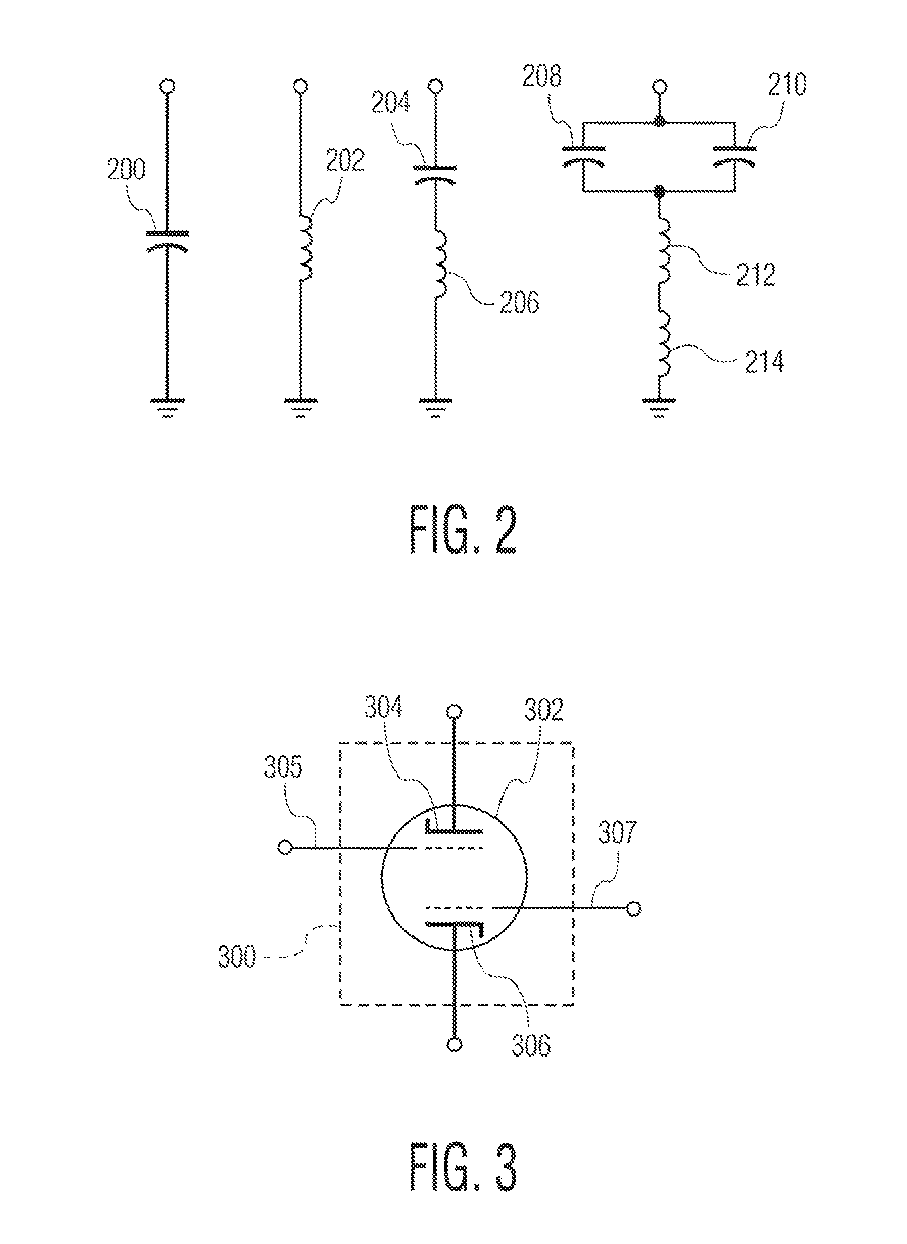
[0034]As used herein, the term “bidirectional high-voltage cold-cathode field-emission electron tube circuit” can refer to a bidirectional high-voltage cold-cathode field-emission electron tube circuit that operates in an analog manner to achieve voltage or current control, depending on the context in which the term is used. Alternatively, the term “bidirectional high-voltage cold-cathode field-emission electron tube circuit” is used to indicate a bidirectional high-voltage cold-cathode field-emission electron tube circuit that can operate in a digital manner and emulate an electrical switch.

General Overview of System for Improving Power Factor

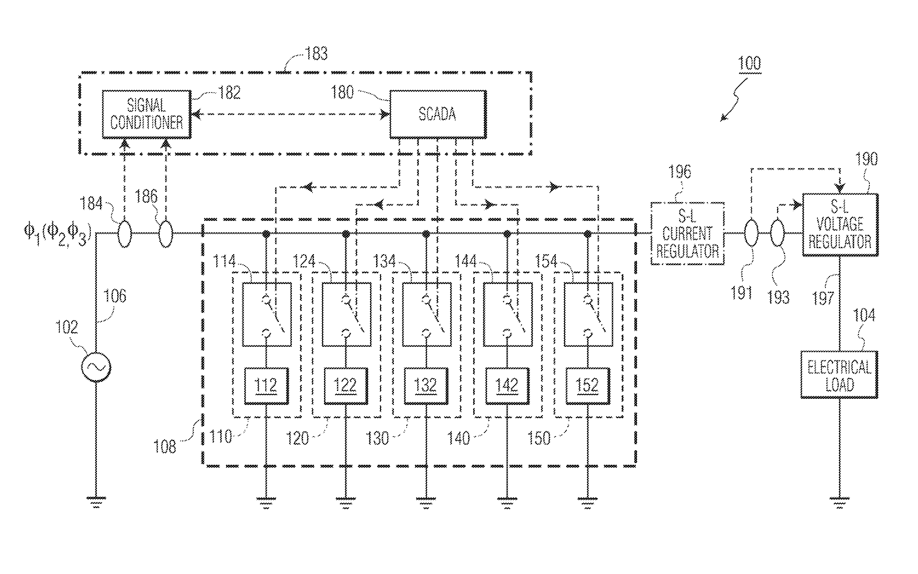
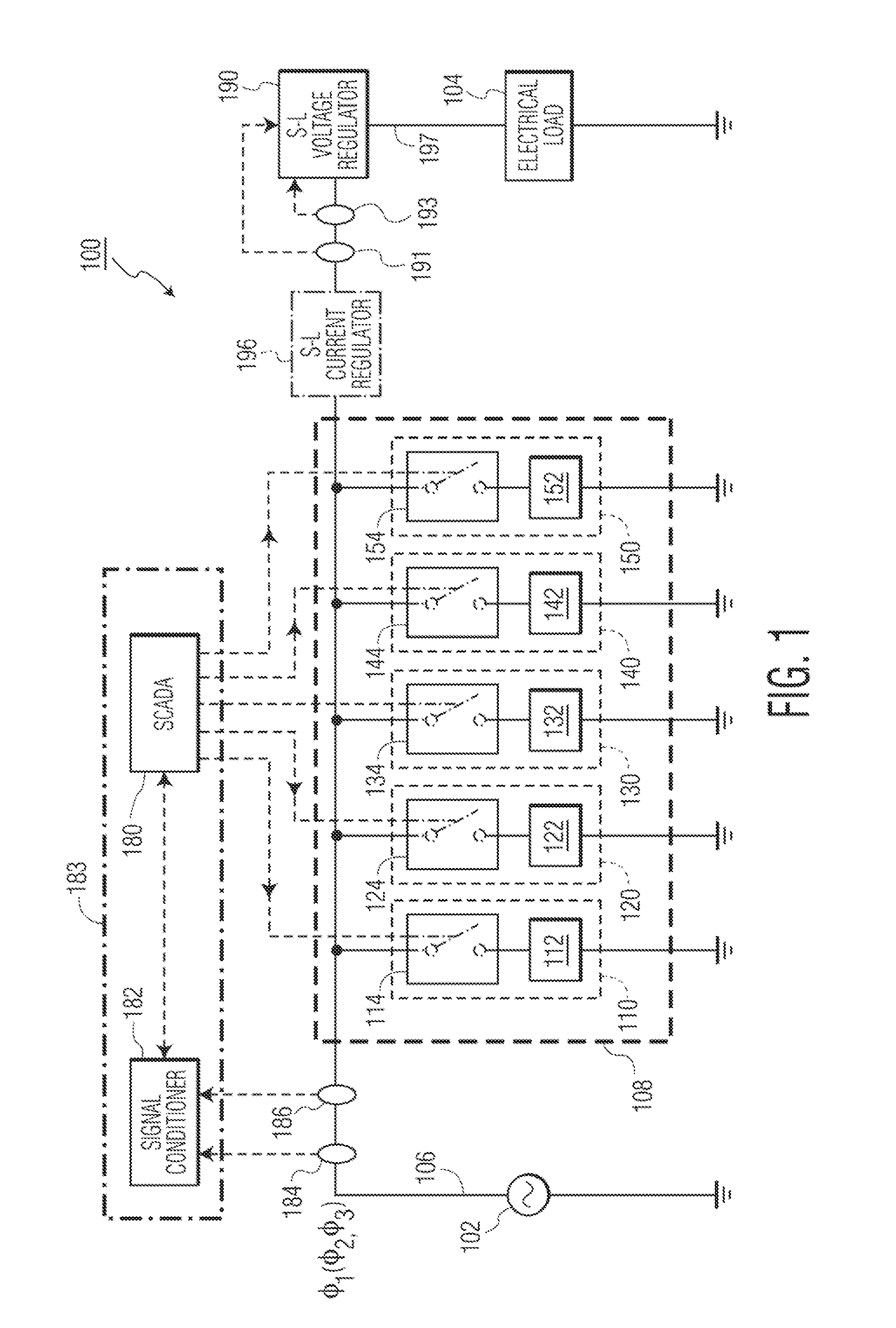
[0035]FIG. 1 shows a single phase of a three-phase AC power system 100 in which an AC power source provides electrical power to an electrical load 104 via a power conveying line 106. AC power source 102 may ...


PUM


Abstract

Disclosed is a system for improving power factor in an AC power system. The power system has an AC power source and an electrical load that are interconnected by at least one power conveying line. The system also comprises a power factor-improving circuit including at least one channel that comprises a channel-level bidirectional electron tube circuit and at least one associated reactive impedance element connected between a power conveying line of the AC power system and ground. Each channel-level bidirectional electron tube circuit is responsive to a control system for connecting or disconnecting at least one associated reactive impedance element when needed for improving power factor. Each channel-level bidirectional electron tube circuit also comprises one bidirectional cold-cathode field-emission electron tube rated at medium to high voltage or two unidirectional cold-cathode field-emission electron tubes rated at medium to high voltage and connected in an anti-parallel manner.

Description

FIELD OF THE INVENTION[0001]The present invention relates to a system for improving power factor in an AC power system.BACKGROUND OF THE INVENTION[0002]The following are definitions of various terms as used herein for better understanding of the inventive system for improving power factor in an AC power system:[0003]1) An “AC power system” connotes herein a source of power and an electrical load that is interconnected by at least one power conveying line. An AC power system may provide power to a single building, for instance, or may provide power to many buildings, as in a power distribution system.[0004]2) A “power conveying line” connotes herein a circuit comprising a set of electrical conductors for conveying power between two points and includes, but is not limited to, a power transmission line or a power distribution line. A power conveying line may be included within a power generation facility itself, or may be used for power transmission or distribution, or may be included ...

Claims


Application Information

Patent Timeline
IPC IPC(8): H02M1/42
CPCH02M1/4208H02J3/1828Y02E40/30Y02B70/10Y02P80/10
Inventor BIRNBACH, CURTIS A
Owner ADVANCED FUSION SYST LLC
Learn More