[0005] In view of the foregoing, the present invention has been devised to substantially eliminate the problems and inconveniences discussed above and is intended to provide an improved inverter power source control circuit for a
high frequency heating apparatus, wherein not only can the power factor of the power source circuit be automatically improved, but the
responsivity and the stability can also be increased.
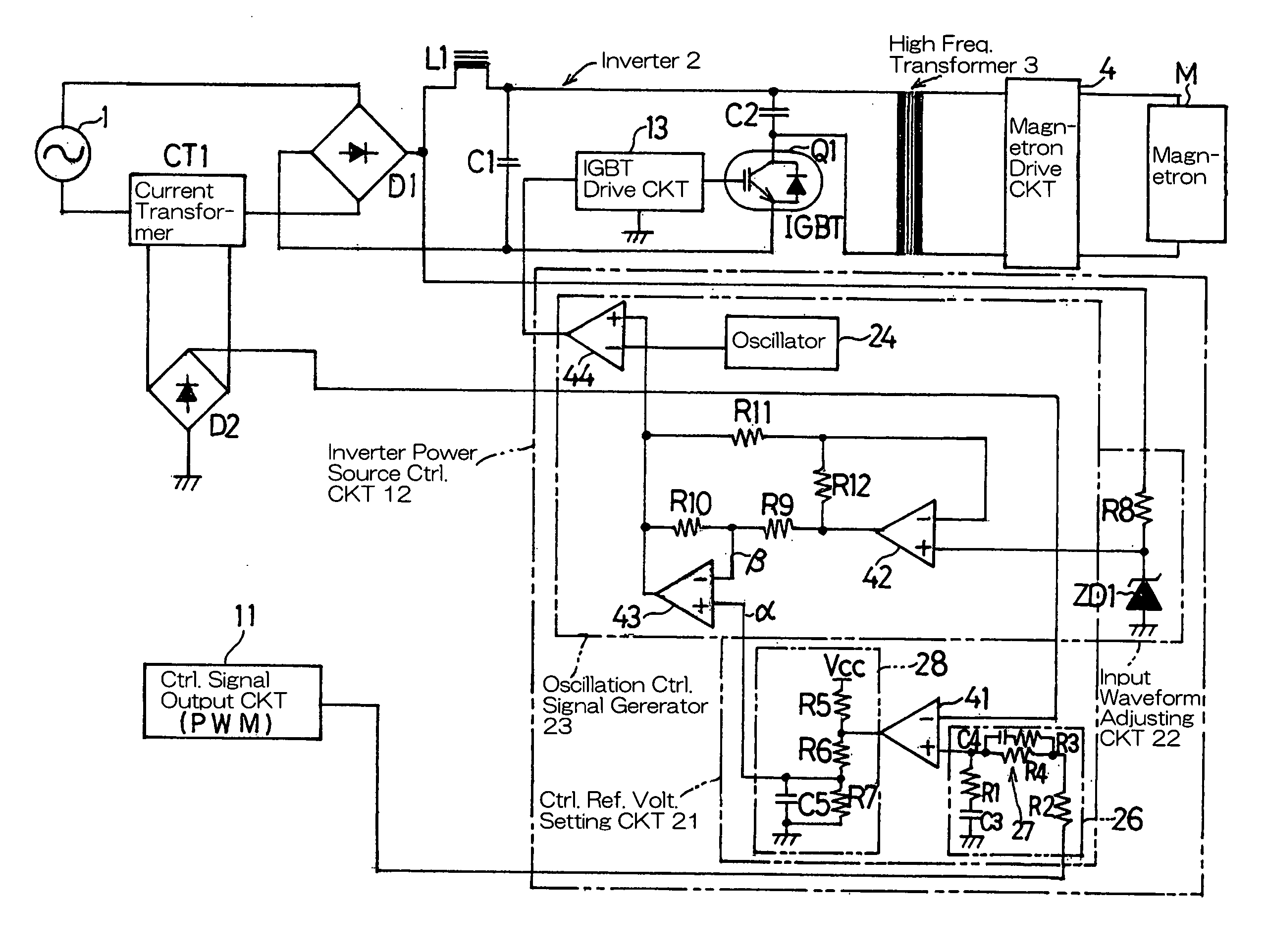
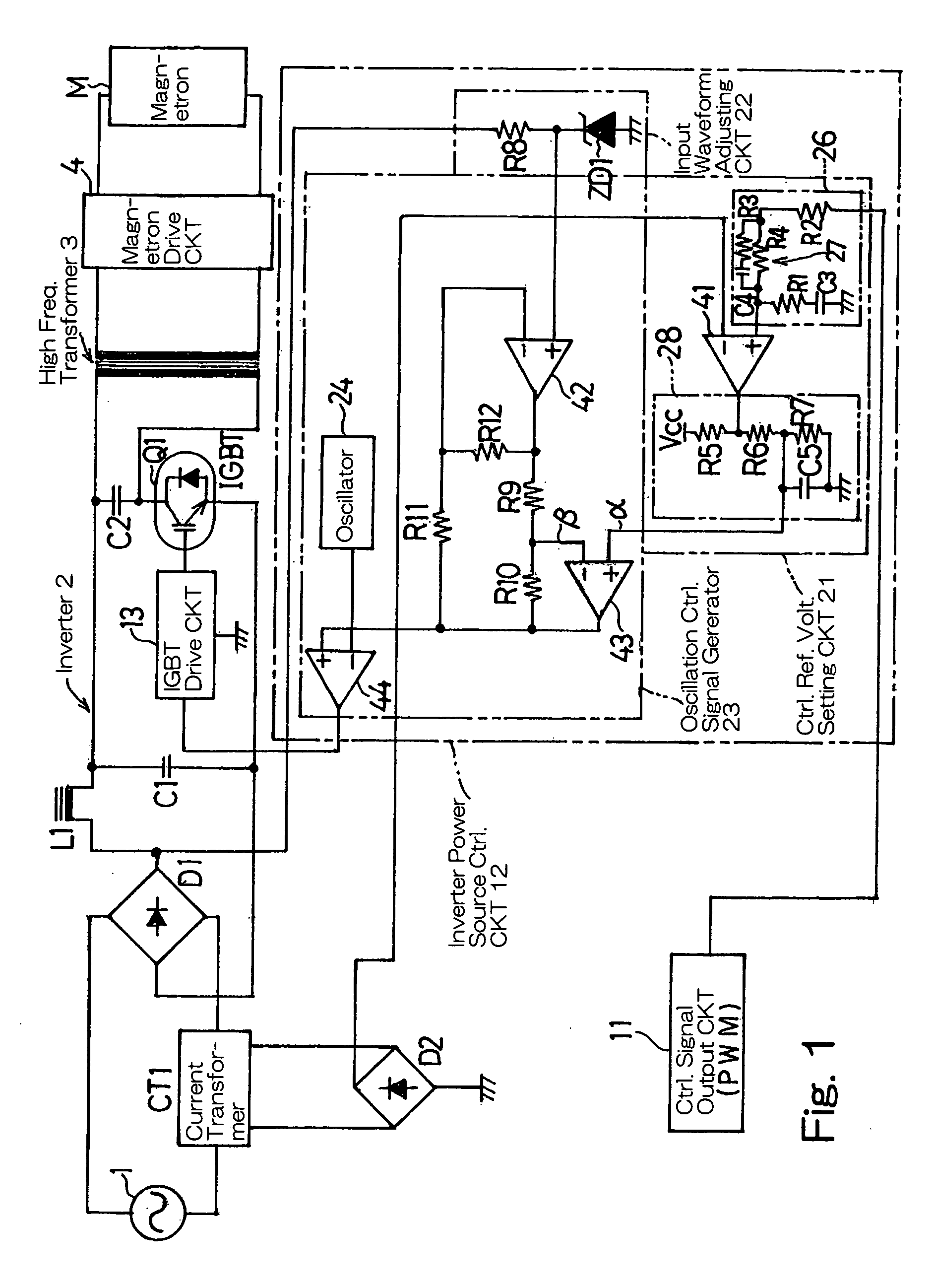
[0006] In order to accomplish the foregoing object, the present invention provides an inverter power source control circuit for a high frequency heating apparatus, which is provided in an inverter power source circuit for supplying an electric power to a magnetron of the high frequency heating apparatus and operable to generate an oscillation control signal by
full wave rectifying and converting an alternating current output from an alternating current power source to a
direct current output and applying the oscillation control signal, based on a PWM control signal through an inverter to a switching element to thereby convert the direct current output to a desired alternating current output. This inverter power source control circuit includes a control reference
voltage setting circuit for outputting a reference
voltage setting signal useable as a benchmark for generation of the oscillation control signal of a voltage set in correspondence with fluctuation of the PWM control signal, wherein by means of the oscillation control signal having the voltage so set, a current waveform of the alternating current output can be approximated to a sinusoidal wave by generating an
electric current at both sides of the current waveform of the alternating current output; an input waveform adjusting circuit for adjusting a peak portion of an input waveform, applied to the inverter to generate a peak adjustment signal required to generate the oscillation control signal, to a sinusoidal wave, wherein by means of the oscillation control signal having this peak adjustment signal, the current waveform of the alternating current output can be approximated to the sinusoidal wave through subtraction of the peak portion of the waveform using the peak adjustment signal of the sinusoidal wave; and an oscillation control signal generating circuit for generating the oscillation control signal based on a
waveform shaping signal, comprised of the reference voltage setting signal and the peak adjustment signal, and a
triangular wave signal from an oscillator, wherein by means of the oscillation control signal containing the reference voltage setting signal and the peak adjustment signal, even though the PWM control signal fluctuates, the current waveform of the alternating current output from the alternating current power source can be approximated to a sinusoidal wave to thereby improve a power factor of an electric power source circuit.
[0007] According to the present invention, since the oscillation control signal generated by the inverter oscillation control circuit includes the reference voltage setting signal, that is used to approximate the current waveform of the alternating current output from the alternating current power source to the sinusoidal wave by generating an
electric current in both sides of the current waveform in correspondence with the fluctuation of the PWM control signal, and the
waveform shaping signal comprised of the peak adjusting signal of a
sinusoidal waveform that is used to approximate to the sinusoidal wave by subtracting a peak portion of the current waveform, the power factor of the electric power source circuit can be automatically improved to a value higher than a predetermined value by approximating the current waveform of the alternating current output from the alternating current power source to the sinusoidal wave even though the PWM control signal fluctuates, therein resulting in increase of the efficiency of the electric power source.
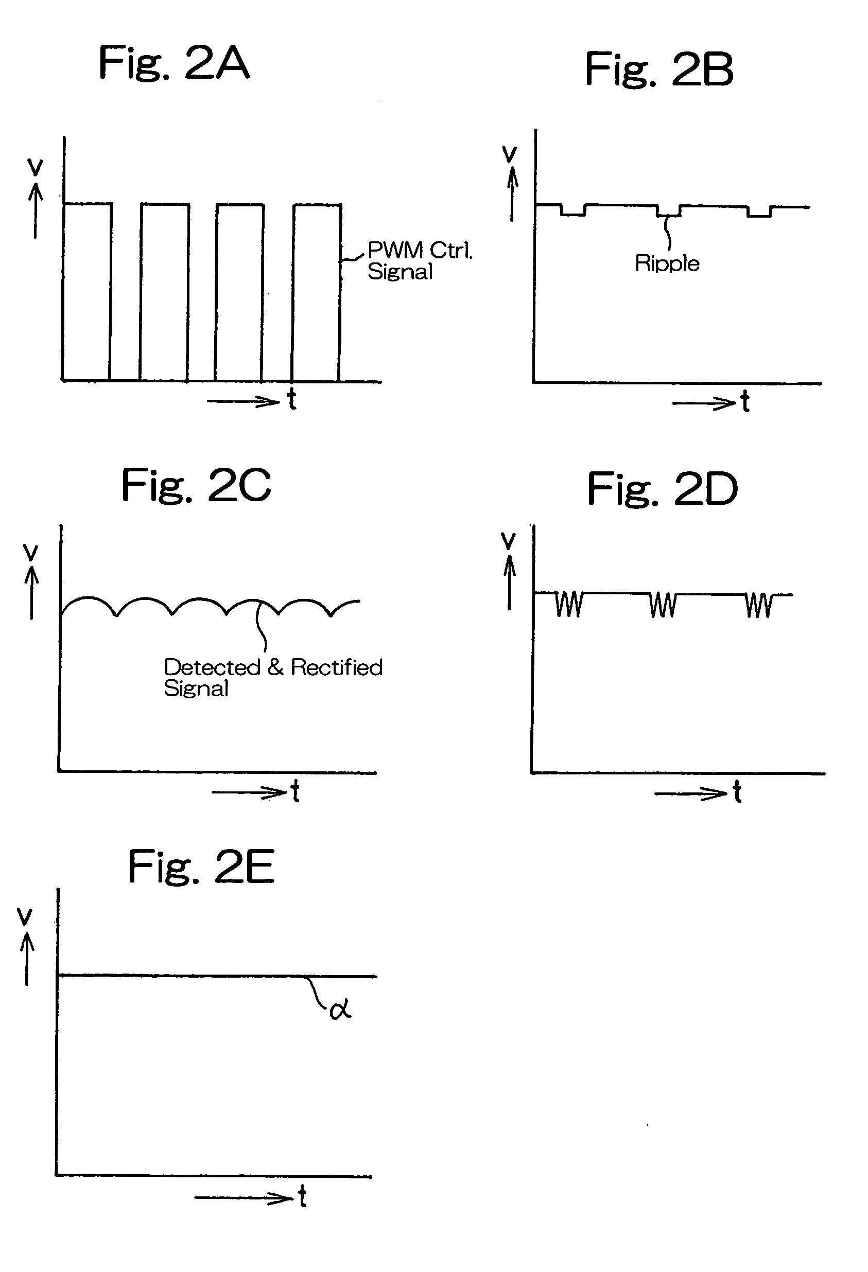
[0008] Preferably the control reference voltage setting circuit may include a
ripple generating circuit for generating a
ripple in one of the PWM control signal or a detected and rectified signal, which is a detected signal outputted from a
current transformer for detecting the alternating current output from the alternating current power source, a first voltage
comparator for comparing the PWM control signal and the detected and rectified signal, either of which contains the
ripple, with each other when the both are applied thereto, and an integrating circuit having a small
time constant for
smoothing an output from the first voltage
comparator. Accordingly, when the PWM control signal and the detected and rectified signal of the alternating current output, one of which is generated with the ripple, is inputted to the first voltage
comparator, a signal of a high frequency can be outputted from the first voltage comparator in the presence of the ripple, that is, comparison of the alternating current outputs is carried out by the first voltage comparator at a
short cycle. Therefore, the
responsivity with the fluctuation of the magnetron output can be increased. Also, the output from the first voltage comparator, when smoothed by the integrating circuit, stabilizes, selection of a relatively small
time constant of the integrating circuit is effective to maintain the
responsivity, and the responsivity and stability in correspondence with the fluctuation of the magnetron output can further be increased.
[0010] In a preferred embodiment of the present invention, the input waveform adjusting circuit may include a
resistor having a
high resistance and a
Zener diode connected in series with the
resistor. In this case, by the utilization of a characteristic of the
Zener diode when the
electric current is lowered with the
resistor having the
high resistance, an input waveform of the
full wave rectified output to be applied to the inverter is adjusted. Accordingly, the voltage obtained by dividing the voltage of the
full wave rectified output with the resistor of a
high resistance and the
Zener diode can be
cut by the Zener
diode to a predetermined value consistent with the characteristic of the magnetron and, also, by the utilization of the characteristic of the Zener
diode, in which when the electric current is reduced across the resistor of a high resistance a voltage exceeding the predetermined voltage is generated, a voltage portion in the vicinity of the voltage so
cut out by the Zener
diode is approximated to the sinusoidal wave. Hence, with the peak adjusted signal based thereon, the current waveform of the alternating current output can be approximated to the sinusoidal wave. Accordingly, with the use of a simple combination of the resistor of a high resistance and the Zener diode, the input waveform adjusting circuit can be realized at a reduced cost.
[0011] In another preferred embodiment of the present invention, the oscillation control generating circuit may include a second voltage comparator and a third voltage comparator, each forming a
differential amplifier. In this case, when a signal having the adjusted input waveform from the inverter and an output from the third voltage comparator are fed to the second voltage comparator, the second voltage comparator outputs the peak adjustment signal and, also, when the reference voltage setting signal from the control reference voltage setting circuit and the peak adjustment signal from the second voltage comparator are fed to the third voltage comparator, the third voltage comparator outputs the waveform shaping signal comprised of the reference voltage setting signal and the peak adjustment signal. Accordingly, with a simplified construction, the oscillation control signal required to approximate the current waveform of the alternating current output from the alternating current power source to the sinusoidal wave can be generated.

