Temperature control system and method thereof

Active Publication Date: 2017-03-23
MICROELECTRONICS TECH INC
View PDF18 Cites 7 Cited by
  • Summary
  • Abstract
  • Description
  • Claims
  • Application Information

AI Technical Summary

Benefits of technology

The patent text is discussing a control system that can work well with different voltage levels and reduce flicker noise to improve power factor control. The technical effect is to provide a more efficient and reliable control system for temperature control.

Problems solved by technology

The liquid or gas typically flows past the heating wire, and energy is then transferred to the medium, by passing current through the wire, thus causing it to heat up.
The non-constant resistance characteristic makes precise temperature control difficult, since the typical way of controlling this type of heater is to turn the heater on or off, using a fixed voltage, AC or DC, thus controlling the duty cycle of the current.
This type of temperature control causes undesired fluctuations in temperature and electrical noise in the system.
Different locations also have varying power available, and fluctuations caused by other equipment attached to the same power can also cause fluctuations in temperature of the liquid or gas.

Method used


Image

  • Temperature control system and method thereof
  • Temperature control system and method thereof
  • Temperature control system and method thereof

Examples


second embodiment

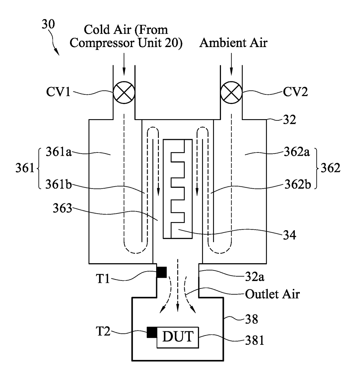
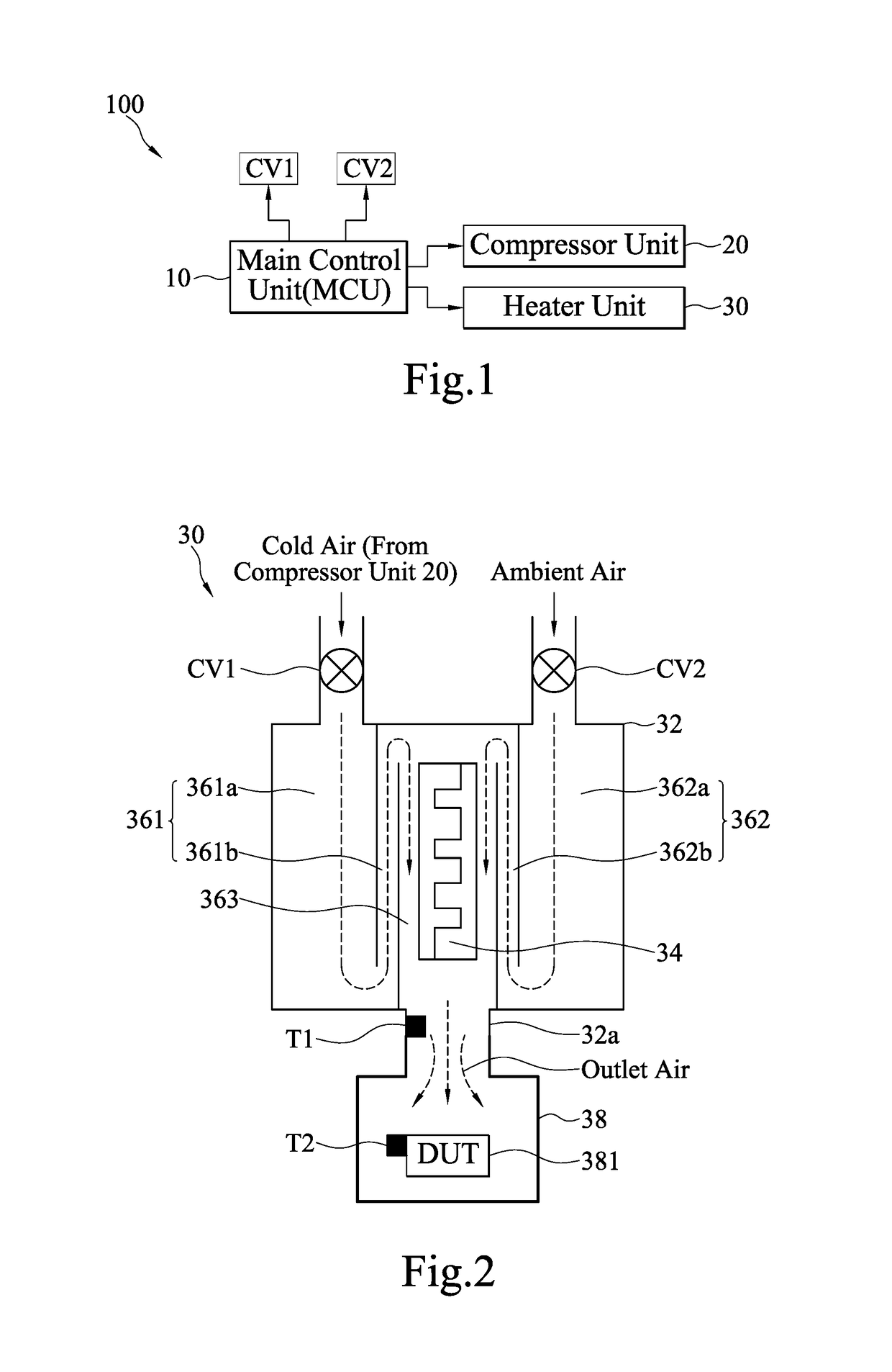
[0032]Furthermore, in the instant disclosure, a control circuit 304 further comprises a second PID controller 33b and an outlet temperature sensor T1 as shown in FIG. 5. The second PID controller 33b is coupled to the first PID controller 33a. In particular, the second PID controller 33b provides a second input signal as the first set point for the first PID controller 33a. The second input signal is based on the difference between a second measurement signal and a second set point. For the instant embodiment, the second measurement signal is produced by the measurement of the outlet temperature of the mixing chamber 32 of the heater unit 30. The measurement can be obtained by the outlet temperature sensor T1 coupled to the mixing chamber 32. Meanwhile, the second set point refers to the desired outlet temperature of the mixing chamber 32. For example, the corresponding powers of the measurement of the outlet temperature of the mixing chamber 32 and the desired outlet temperature an...

third embodiment

[0033]Another example of the instant disclosure is shown by a control circuit 306 in FIG. 6. Also adopting the cascade control scheme, the system 306 further includes a third PID controller 33c and a DUT temperature sensor T2. Like the previous embodiment, the third PID controller 33c is coupled to the first PID controller 33a. In particular, the third PID controller 33c provides a third input signal as the first set point for the first PID controller 33a. The third input signal is based on the difference between a third measurement signal and a third set point. For the instant embodiment, the third measurement signal is produced by the temperature measurement of the DUT, where the measurement can be obtained by the DUT temperature sensor T2 coupled to a DUT 381. The third set point refers to the desired temperature of the DUT 381 and can be given by the user. For example, the corresponding powers of the temperature measurement of the DUT 381 and the desired temperature of the DUT 3...

fourth embodiment

[0034]In a fourth embodiment as shown in FIG. 7, a control circuit 308 incorporates both the second PID controller 33b and third PID controller 33c. That is the third PID controller 33c is coupled to the second PID controller 33b, which is coupled to the first PID controller 33a. The third PID controller 33c provides the third input signal as the second set point for the second PID controller 33b, and the second PID controller 33b provides the second input signal as the first set point for the first PID controller 33a. The characteristics of the second and third input signal have already been explained in previous paragraphs, thus not further elaboration will be given here. Based on FIGS. 5-7, these multi-looped circuits provide alternative temperature control strategies. It should be noted that additional PID controller may be added depending on a user preference. For example, another PID controller may be utilized to control the heating process according to the mass flow rate of t...


PUM


Abstract

A temperature control system and method are provided. The system includes a first channel, a second channel, a heating element, a DUT chamber, a converter, a first PID controller, and at least one switching regulator. The heating element is disposed downstream of the first and the second channels to heat the first air from the first channel or the second air from the second channel according to an input power so as to provide mixing air with a temperature into the DUT chamber. The converter converts an AC power to a DC power. The first PID controller provides a first input signal according to a first set point and an amount of power consumed by the heating element. The input power is adjusted by the switching regulator to drive the heating element according to the first input signal. Thus, the use of electrical power is more efficient.

Description

CROSS-REFERENCES TO RELATED APPLICATIONS[0001]This non-provisional application claims priority under 35 U.S.C. §119(a) on U.S. Provisional Patent Application No. 62 / 219,709, filed on Sep. 17, 2015, the entire contents of which are hereby incorporated by reference.BACKGROUND[0002]Technical Field[0003]The instant disclosure relates to temperature control, in particular to a temperature control system and method with improved electrical power management.[0004]Related Art[0005]In the field of thermal management of a liquid or gas flow, temperature control via a heating device has been around for a long time. The power requirement is variable, depending on the amount of flow, desired temperature range, and the temperature change rate. Heating elements are normally resistance based, typically using tungsten wire to provide the resistance element. The liquid or gas typically flows past the heating wire, and energy is then transferred to the medium, by passing current through the wire, thus...

Claims


Application Information

Patent Timeline
IPC IPC(8): G01R31/28H05B1/02F24H9/20
CPCG01R31/2875H05B1/0297F24H9/2071G01R31/2862G05D23/20F24H15/144F24H15/20F24H15/281F24H15/414
Inventor KRYSTAD, HELGE JACOBCHANG, YING-CHIAOLEE, YUEH-YING
Owner MICROELECTRONICS TECH INC
Why Eureka
Try Eureka