Liquid crystal display and display panel thereof

a technology of liquid crystal display panel and display panel, which is applied in the direction of instruments, static indicating devices, etc., can solve the problems of increasing the complexity of the design of the gate driver also increases, and the flicker noise is more serious in the larger display panel size, so as to reduce the problem of feed-through effect and simple design of the circuit on the gate driver

Active Publication Date: 2008-10-02
CHUNGHWA PICTURE TUBES LTD
View PDF4 Cites 10 Cited by
  • Summary
  • Abstract
  • Description
  • Claims
  • Application Information

AI Technical Summary

Benefits of technology

[0015]Accordingly, the present invention is directed to a display panel with many switch units for controlling the time points at that the pixel row units receive the common voltage of the display panel. Thus, the common voltage of the display panel is maintained at an optimal potential, and the design of the circuit on the gate driver is simple. At the result, the problems caused by the feed-through effect may be effectively reduced.

Problems solved by technology

With the development of the semiconductor technology, several large size liquid crystal displays have been developed, but which also poses another technical challenge, namely flicker noise tends to be more serious in larger size display panel.
However, it must perform a complicated hand measurement to determine the optimum common voltage V′com provided to the display panel at the beginning of modifying the common voltage Vcom by the related method 1.
Furthermore, the properties of each display panel are not completely the same, so the optimum common voltage V′com determined above will not meet completely each display panel.
Thus, during the period of increasing the accuracy on the compensating voltage VP, the complexity of the design on the gate driver is also increased.
Therefore, when the related method 2 eliminates the flicker noise of the liquid crystal display, the complexity of the design on the gate driver is also increased.
As the result, the liquid crystal display will have more layout area and more waste of the power.

Method used


Image

  • Liquid crystal display and display panel thereof
  • Liquid crystal display and display panel thereof
  • Liquid crystal display and display panel thereof

Examples


Embodiment Construction

[0035]Reference will now be made in detail to the present preferred embodiments of the invention, examples of which are illustrated in the accompanying drawings. Wherever possible, the same reference numbers are used in the drawings and the description to refer to the same or like parts.

[0036]The main technical features of the present invention are that pixel row units may selectively receive the common voltage from a display panel in conjunction with the conductive state between two ends of switch units, thereby the flicker noise caused by a feed-through effect may be eliminated. The display panel and the liquid crystal display of the present invention will be explained below, however, this is not intended to limit the scope of the present invention, it will be understood by those of ordinary skill in the art that various changes in form and details may be made therein without departing from the spirit and scope of the present invention.

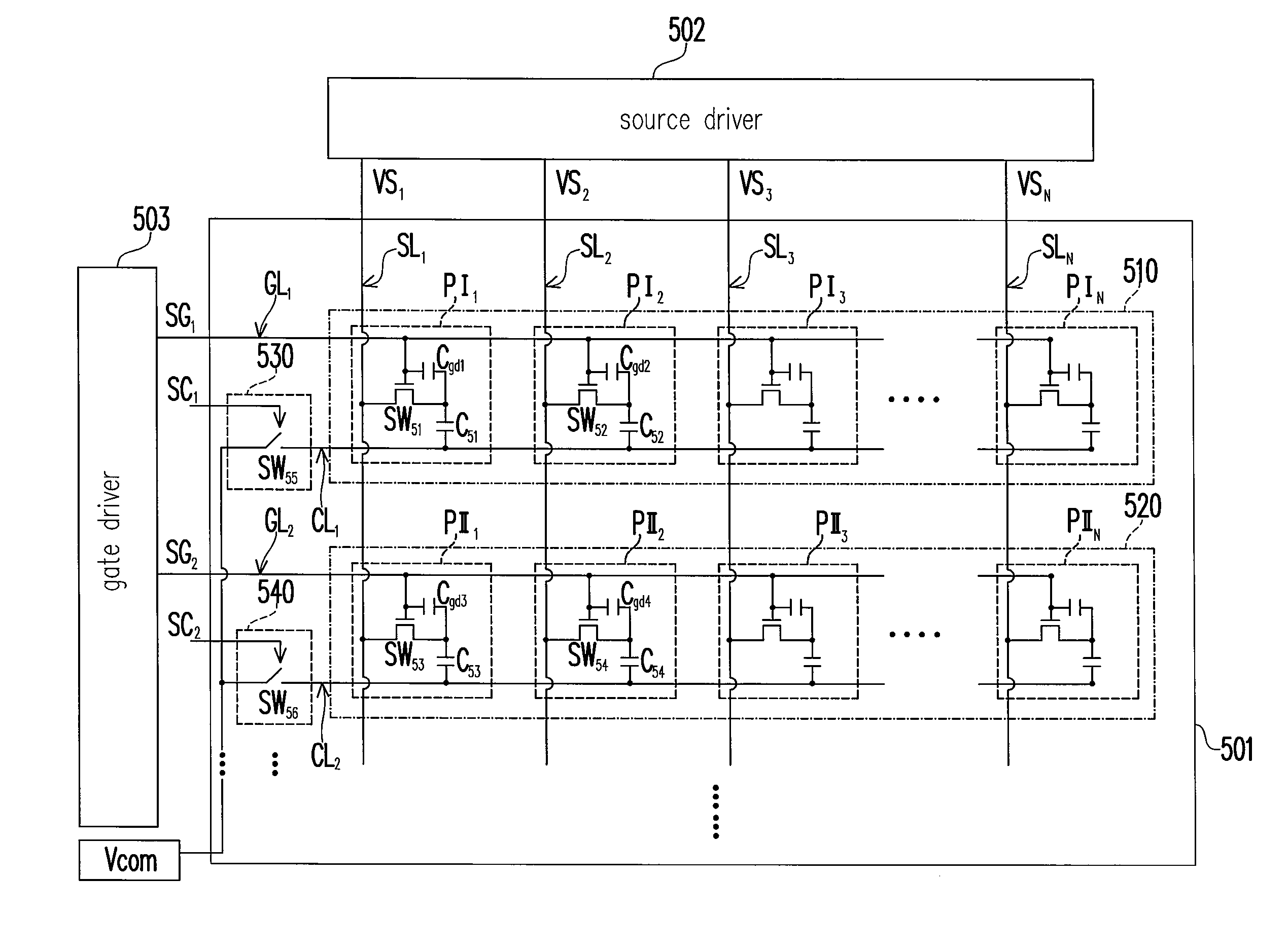
[0037]FIG. 5 is a schematic view illustrating...


PUM


Abstract

A liquid-crystal-display (LCD) and a display panel thereof are provided. The display panel includes a plurality of pixel row units and a plurality of switch units. Each pixel row unit is connected between a scan line and a potential switch line. The first end of each switch unit receives the common voltage provided by the display panel, and the second end of each switch unit is connected to its corresponding potential switch line. Thus, not only the flicker-noise of the display panel is reduced, but also the display-quality of the LCD is promoted.

Description

CROSS-REFERENCE TO RELATED APPLICATION[0001]This application claims the priority benefit of Taiwan application serial no. 96110706, filed on Mar. 28, 2007. All disclosure of the Taiwan application is incorporated herein by reference.BACKGROUND OF THE INVENTION[0002]1. Field of the Invention[0003]The present invention generally relates to a liquid crystal display and display panel thereof, and more particularly, to a liquid crystal display and display panel thereof which may selectively receive a common voltage by using pixel row units.[0004]2. Description of Related Art[0005]Nowadays, a liquid crystal display (LCD) is widely used, and has replaced cathode ray tube (CRT) display. Therefore, it has become one of the mainstream display for the next generation displays. With the development of the semiconductor technology, several large size liquid crystal displays have been developed, but which also poses another technical challenge, namely flicker noise tends to be more serious in lar...

Claims


Application Information

Patent Timeline
Patent Type & Authority Applications(United States)
IPC IPC(8): G09G3/36
CPCG09G3/3655G09G2320/0219G09G2320/0247
Inventor TU, CHANG-CHINGFANG, YU-CHIEH
Owner CHUNGHWA PICTURE TUBES LTD
Why Eureka
Try Eureka