Receiver apparatus, reception method, communication system, and communication method

a technology of receiving apparatus and communication system, applied in the field of receiving apparatus, a reception method, a communication system, and a communication method, can solve the problems of greatly degrading transmission performance, and achieve the effect of substantially increasing the accuracy of channel estimation

Active Publication Date: 2013-11-21
SHARP KK
View PDF4 Cites 22 Cited by
  • Summary
  • Abstract
  • Description
  • Claims
  • Application Information

AI Technical Summary

Benefits of technology

[0016]According to the present invention, accuracy of the channel estimation is substantially increased.

Problems solved by technology

Since the receiver apparatus performs demodulation and decoding using channel estimation results, transmission performances are greatly degraded if the accuracy of the channel estimation is decreased.

Method used


Image

  • Receiver apparatus, reception method, communication system, and communication method
  • Receiver apparatus, reception method, communication system, and communication method
  • Receiver apparatus, reception method, communication system, and communication method

Examples


first embodiment

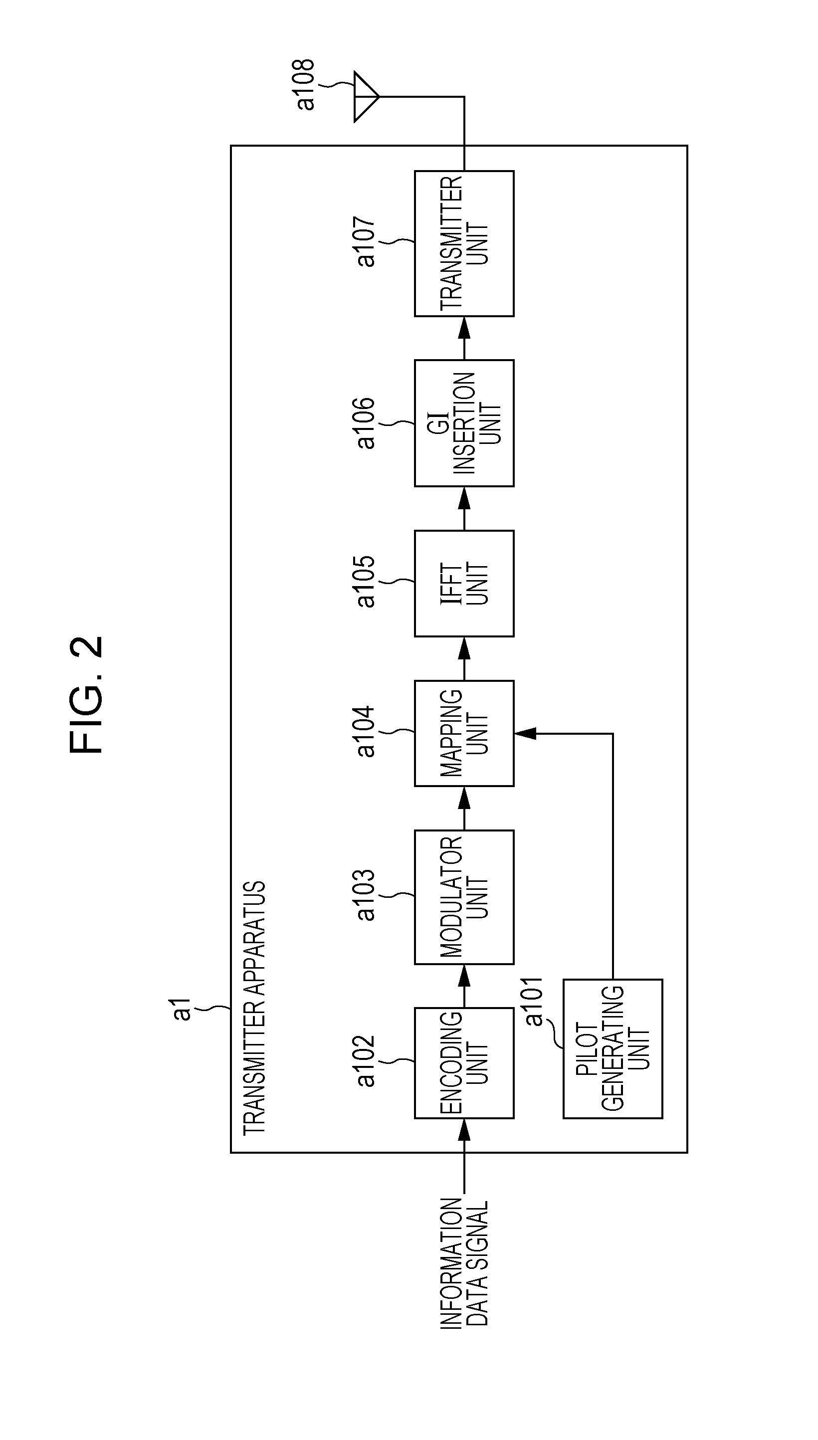
[0032]FIG. 2 is a schematic block diagram illustrating a transmitter apparatus of a first embodiment of the present invention. In the present embodiment, a transmitter apparatus a1 is described. In FIG. 2, the transmitter apparatus a1 includes a pilot generating unit a101, an encoding unit a102, a modulator unit a103, a mapping unit a104, an IFFT (Inverse Fourier Transform) unit (also referred to as a frequency-time transform unit) a105, a GI (Guard Interval) insertion unit a106, a transmitter unit a107, and a transmit antenna a108. The transmitter apparatus a1 transmits an OFDM signal.

[0033]The pilot generating unit a101 generates a pilot symbol. An amplitude value of a waveform (or a signal sequence) of the pilot symbol is pre-stored on a receiver apparatus. The pilot generating unit a101 outputs the pilot symbol to the mapping unit a104. In the discussion of the present embodiment, a receiver apparatus b1 is used as the receiver apparatus. The receiver apparatus b1 performs chann...

second embodiment

[0095]A second embodiment of the present invention is described in detail with reference to the drawings. In the first embodiment, the transmitter apparatus a1 transmits a multi-carrier signal and the like, which map the pilot signal to the frequency domain, the receiver apparatus b1 calculates the frequency response estimation value in the pilot subcarrier, calculates the interim channel impulse response estimation value by performing the IFFT operation on the frequency response estimation value, selects a path having a higher power, and then calculates the channel impulse response estimation value using the path. The present embodiment provides a method of performing the channel impulse response estimation on a plurality of extracted paths and selecting an optimum path.

[0096]A transmitter apparatus a2 of the second embodiment is identical to the transmitter apparatus a1 of the first embodiment, and the discussion thereof is omitted herein.

[0097]FIG. 10 is a schematic block diagram...

third embodiment

[0122]A third embodiment of the present invention is described in detail with reference to the drawings. In the channel estimator of the second embodiment, the transmitter apparatus a1 transmits the multi-carrier signal and the like, which map the pilot signal to the frequency domain, the receiver apparatuses b1 and b2 calculate the frequency response estimation value in the pilot subcarrier, calculate the interim channel impulse response estimation value by performing the IFFT operation on the frequency response estimation value, perform the extraction of a path having a higher power by multiple times, select the best path, and then calculate the channel impulse response using the selected extracted path. In the present embodiment, all paths from a preceding path to a path having an assumed maximum delay time are estimated, an operation to reduce the number of paths is performed, and if the reduction operation proves satisfactory, a remaining path as a result of the reduction opera...


PUM


Abstract

A receiver apparatus includes a channel estimator (b106) to perform channel estimation. The channel estimator includes an interim channel impulse estimating unit (b106-1) that calculates an interim channel impulse response estimation value, a path extracting unit (b106-3) that extracts a path for use in calculation of a channel impulse response estimation value from among paths forming the interim channel impulse response estimation values, a channel impulse response estimating unit (b106-4) that calculates the channel impulse response estimation value using the path extracted by the path extracting unit, and a frequency response estimating unit (b106-5) that converts the channel impulse response estimation value into a frequency response estimation value by time-frequency transforming the channel impulse response estimation value. In this way, a receiver apparatus capable of performing accurate channel estimation results.

Description

TECHNICAL FIELD[0001]The present invention relates to a receiver apparatus, a reception method, a communication system, and a communication method.BACKGROUND ART[0002]In the field of radio communications, a receiver apparatus performs channel estimation to learn a radio channel state. Since the receiver apparatus performs demodulation and decoding using channel estimation results, transmission performances are greatly degraded if the accuracy of the channel estimation is decreased. To perform accurate channel estimation, statistic property of a channel needs to be identified. The statistic property of the channel includes power of a path forming a channel, and a delay time from a previously received path. FIG. 1 illustrates an example of a channel impulse response of a channel in the time domain, and arrows labeled 100-1 through 100-8 denote paths. Labels 100-4 and 100-5 are intended to mean delay times where no significant paths are present. Such a location is herein interpreted as...

Claims


Application Information

Patent Timeline
Patent Type & Authority Applications(United States)
IPC IPC(8): H04L25/02
CPCH04L25/0212H04L25/022H04L27/2649
Inventor KATO, KATSUYAYOSHIMOTO, TAKASHIYAMADA, RYOTA
Owner SHARP KK
Why Eureka
Try Eureka