Fan bearing retaining structure

a technology of bearing retaining structure and fan bearing, which is applied in the direction of liquid fuel engines, machines/engines, mechanical equipment, etc., can solve the problems difficult to control the tightness of fittings, and formation of shrinkage holes on bearings, so as to reduce assembly time and labor, effectively retaining bearings, and improve the accuracy of fittings

Active Publication Date: 2013-11-21
ASIA VITAL COMPONENTS SHENZHEN CO LTD
View PDF9 Cites 1 Cited by
  • Summary
  • Abstract
  • Description
  • Claims
  • Application Information

AI Technical Summary

Benefits of technology

[0007]A primary object of the present invention is to provide a fan bearing retaining structure for effectively retaining a bearing in a bearing cup of a fan.
[0008]Another object of the present invention is to provide a fan bearing retaining structure that enables improved fitting accuracy and fitting allowance between a bearing and a bearing cup.
[0009]A further object of the present invention is to provide a fan bearing retaining structure that enables reduced assembling time and labor and accordingly reduced manufacturing cost of a fan.
[0010]To achieve the above and other objects, the fan bearing retaining structure according to the present invention includes a base and a ring member. The base has a bearing cup projected from one side thereof, and the bearing cup internally defines an axial bore for receiving a bearing therein. The ring member is fitted around an outer side of the bearing cup and defines an opening, such that an inner side of the opening tightly contacts with the outer side of the bearing cup to apply a radially inward compression on the axial bore. With these arrangements, a portion of the axial bore corresponding to the ring member fitted around the bearing cup has a reduced inner diameter to thereby effectively retain the bearing in the bearing cup, enabling a fan to be manufactured at lowered cost.

Problems solved by technology

This is because the plastic material is subject to thermal expansion and cold contraction, and it is therefore difficult to control correct fitting tightness and required range of fitting allowance between the bearing and the central tube in the process of manufacturing the bearing and the central tube.
That is, it is uneasy to achieve proper fit between the bearing and the central tube.
For example, in the event the bearing is too tightly fitted in the central tube, it would result in the formation of shrinkage holes on the bearing.
On the other hand, in the event the bearing is too loosely fitted in the central tube, it would not be able to effectively hold the bearing in place in the central tube and result in low fitting accuracy and poor fitting allowance.
Thus, the conventional way of forming a fan through plastic injection-molding fails to effectively hold the bearing in place in the central tube, and it is uneasy to control the fitting accuracy between the bearing and the central tube in the manufacturing process.
These drawbacks in turn cause unstable operation of the fan motor.
However, the metal central tube involves relatively complicated structure and machining procedures.
Therefore, the use of the metal central tube inevitably increases the overall manufacturing cost of the fan.
In brief, the prior art fan bearing retaining structures have the following disadvantages: (1) having low fitting accuracy and poor fitting allowance between the bearing and the plastic central tube; (2) failing to effectively hold the bearing in place to thereby cause vibration of motor; (3) requiring increased cost for manufacturing a metal central tube for stably holding a bearing therein; and (4) involving complicated manufacturing processes and accordingly increased labor and time.

Method used


Image

  • Fan bearing retaining structure
  • Fan bearing retaining structure
  • Fan bearing retaining structure

Examples


Embodiment Construction

[0025]The present invention will now be described with some preferred embodiments thereof and with reference to the accompanying drawings. For the purpose of easy to understand, elements that are the same in the preferred embodiments are denoted by the same reference numerals.

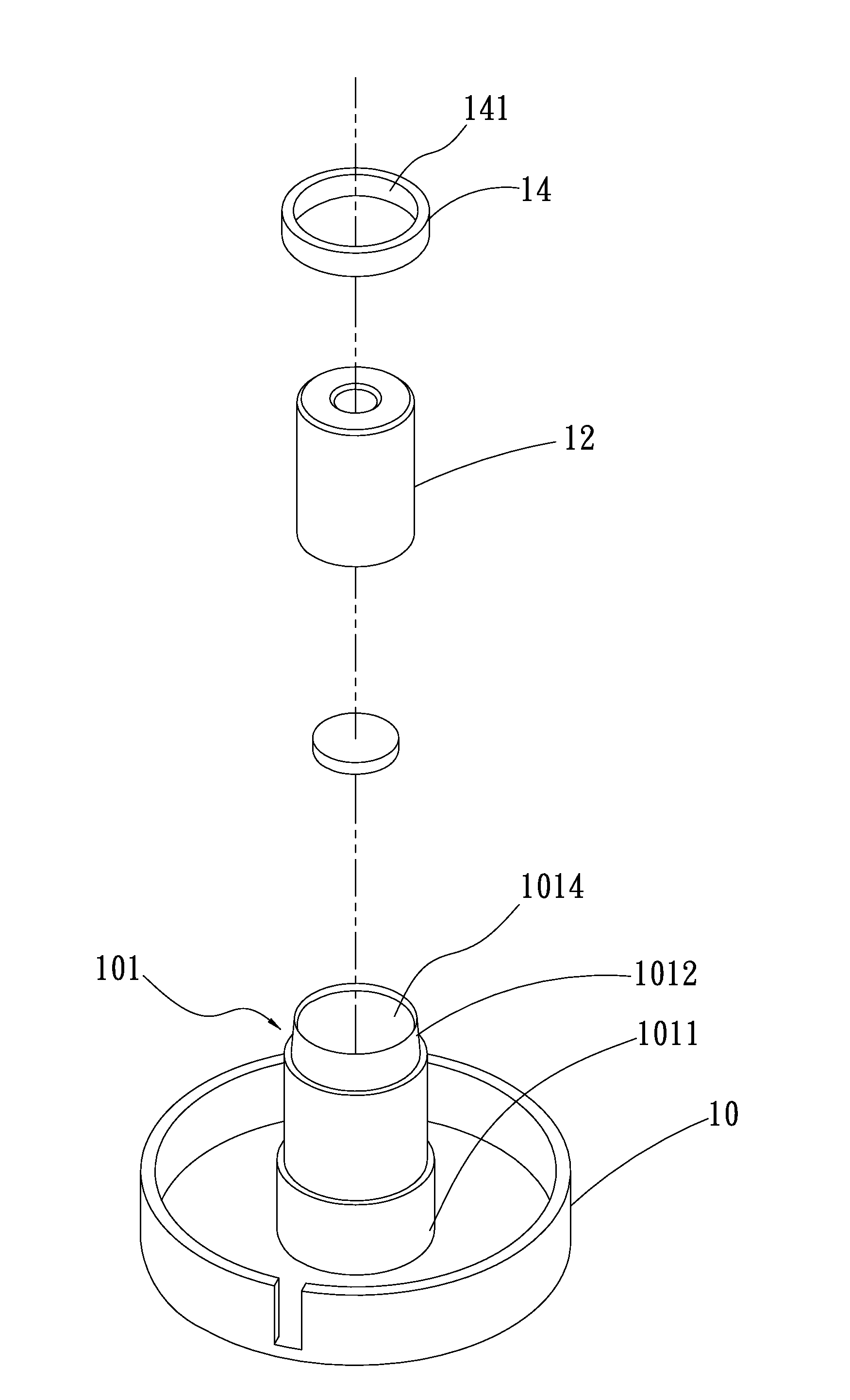
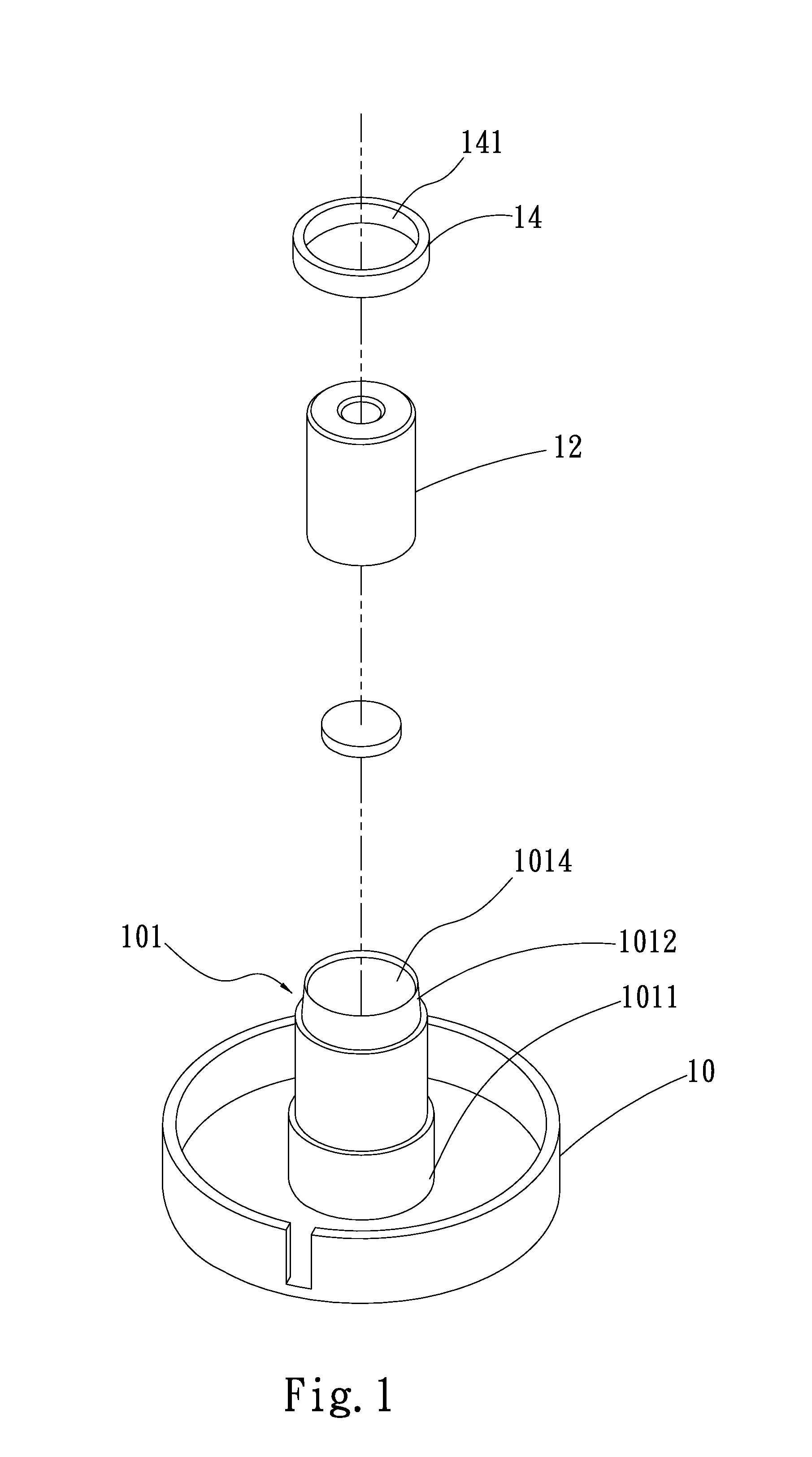
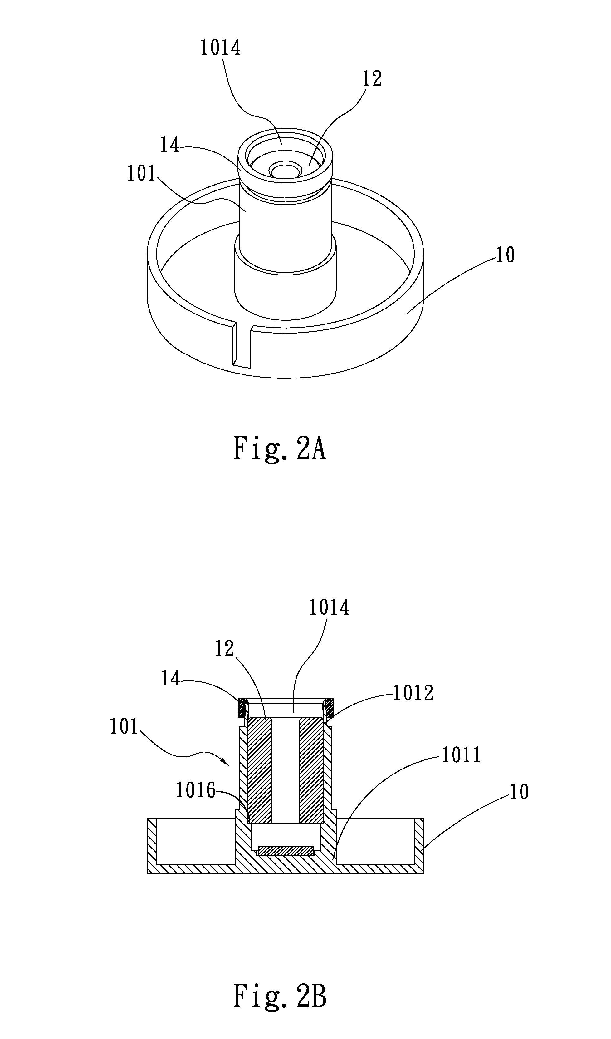
[0026]Please refer to FIGS. 1 and 2A that are exploded and assembled perspective views, respectively, of a fan bearing retaining structure according to a first preferred embodiment of the present invention; and to FIG. 2B that is a sectional view of FIG. 2A. As shown, the fan bearing retaining structure in the first preferred embodiment includes a base 10 and a ring member 14. The base 10 includes a bearing cup 101 projected from one side of the base 10. The bearing cup 101 internally defines an axial bore 1014 and a shoulder portion 1016. The shoulder portion 1016 radially inward protrudes from an inner side of the bearing cup 101 toward a center of the axial bore 1014. A bearing 12 is received in the axial bo...


PUM


Abstract

A fan bearing retaining structure includes a base and a ring member. The base has a bearing cup projected from one side thereof, and the bearing cup internally defines an axial bore for receiving a bearing therein. The ring member is fitted around an outer side of the bearing cup and defines an opening, such that an inner side of the opening tightly contacts with the outer side of the bearing cup to apply a radially inward compression toward the axial bore. With these arrangements, a portion of the axial bore corresponding to the ring member fitted around the bearing cup has a reduced inner diameter to thereby effectively retain the bearing in the bearing cup, enabling a fan to be manufactured at reduced cost.

Description

FIELD OF THE INVENTION[0001]The present invention relates to a bearing retaining structure, and more particularly to a fan bearing retaining structure that effectively retains a bearing in a bearing cup at reduced manufacturing cost to avoid the problem of a loose bearing in the bearing cup of a fan.BACKGROUND OF THE INVENTION[0002]Many devices, such as fans, use a motor to achieve the purpose of transmission. Therefore, the quality of a motor plays a very important role in the performance of a motor-driven device. A motor failing to work stably would no doubt adversely affect the whole operation of the device. Among others, the bearing is one of the most important factors that have influence on the quality of a motor.[0003]Conventionally, a fan is formed by injection molding a plastic material. In the manufacturing process of the fan, a central tube of the fan is integrally injection molded along with a bearing, so that the bearing is fixedly held in the central tube to allow stabl...

Claims


Application Information

Patent Timeline
Patent Type & Authority Applications(United States)
IPC IPC(8): F04D29/04
CPCF04D29/04F04D25/062F04D25/0613F04D29/0462F04D29/056F04D29/046F04D29/0563
Inventor CHOU, CHU-HSIENHONG, SHAO-JUN
Owner ASIA VITAL COMPONENTS SHENZHEN CO LTD
Why Eureka
Try Eureka