Orthopaedic device and method of use for treating bone fractures
a technology of orthopaedic devices and bone fractures, which is applied in the field of orthopaedic devices, can solve the problems of difficult to maintain difficulty in adjusting the position of the device, and difficulty in maintaining the pressure applied to the soft tissue using such devices, so as to achieve the effect of convenient adjustment of positioning
- Summary
- Abstract
- Description
- Claims
- Application Information
AI Technical Summary
Benefits of technology
Problems solved by technology
Method used
Image
Examples
first embodiment
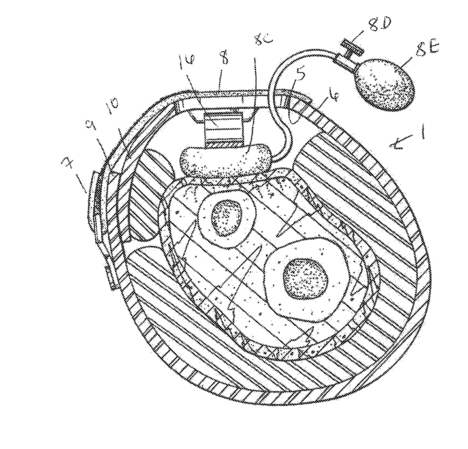
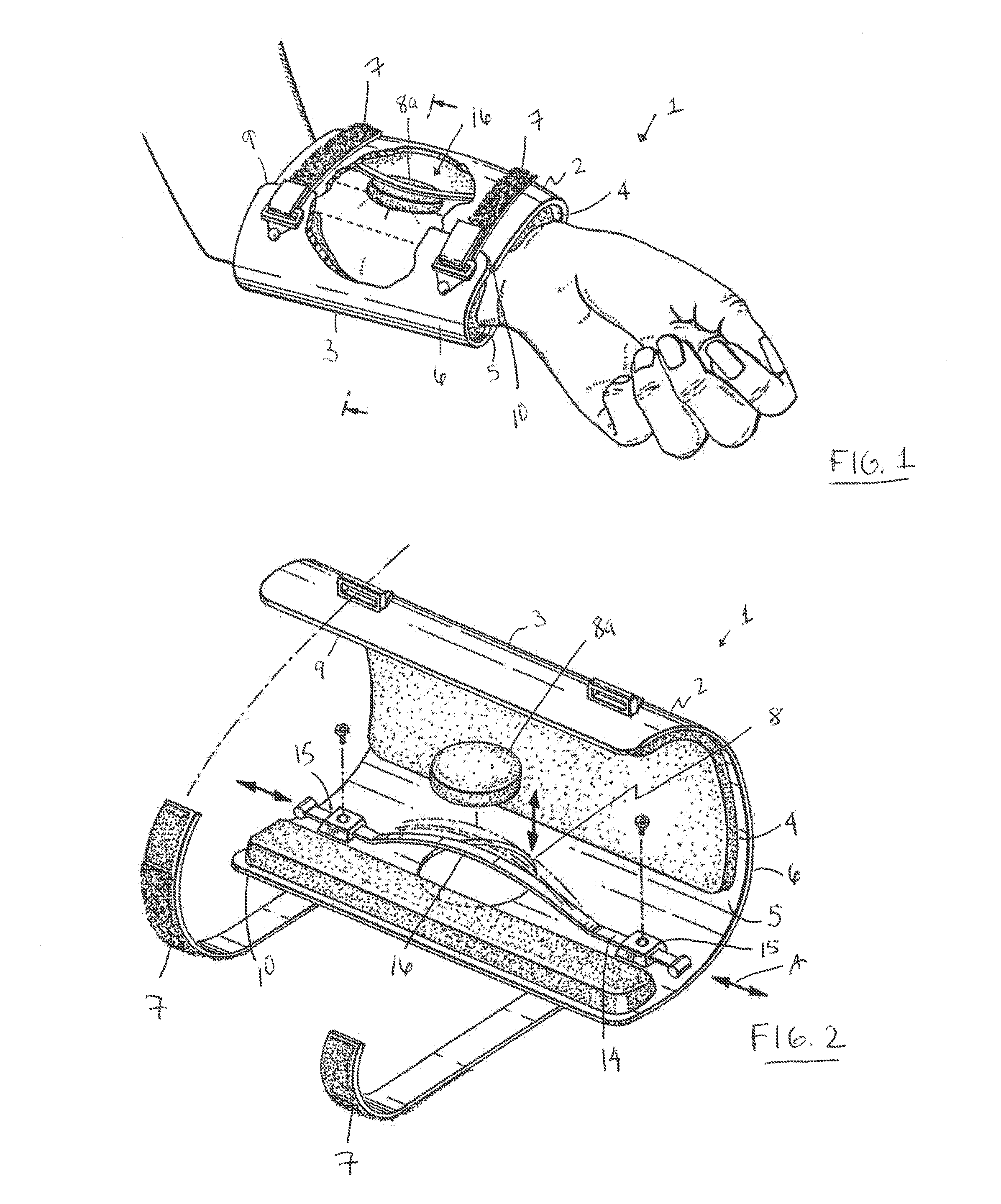
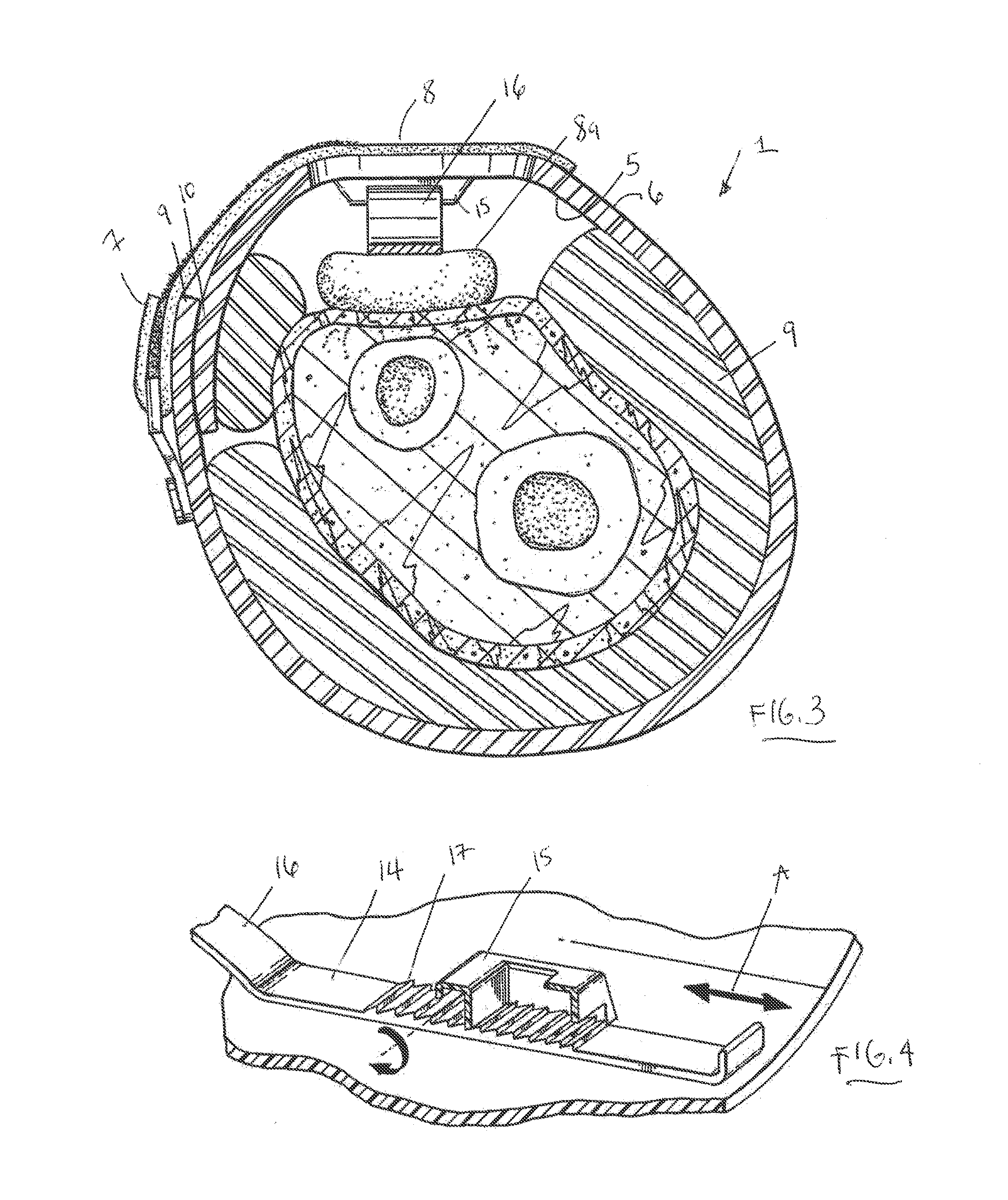
[0026]In a first embodiment, orthopaedic device 1, described below with reference to FIGS. 1-3, 5, 7A, 7B and 15-18, includes one or more pressure applying elements 16 and a holder 2.
[0027]The one or more pressure applying elements 16, to be described in detail below, is configured to be adjustably positioned on to the holder 2 and configured to adjustably apply pressure to the soft tissue adjacent to the bone fracture.
[0028]The holder 2 is configured to be positioned onto a target body part and to engage soft tissue adjacent to a bone fracture. It is understood that although the holder 2 is illustrated in the figures as a brace, the holder 2 may alternatively be a splint, a cast, a bandage, or a structural member that surrounds a body part, in whole or in part.
[0029]As illustrated in FIGS. 1 and 2, the holder 2 has, for example, a formed open shell configuration along a longitudinal direction 3 that defines a first edge 9 and a second edge 10. The open shell configuration of the ho...
second embodiment
[0055]In a second embodiment, an orthopaedic device 1 includes a holder 2 and a mechanical pressure applying element 16. The mechanical pressure applying element 16 is supported by and / or connected to the holder 2 and is configured to apply and maintain a desired pressure directly against the soft tissue or indirectly against the soft tissue through an intermediary contact material 8a.
[0056]FIG. 2 illustrates a first example of a mechanical pressure applying element 16 comprising a strip 14 that is relatively flexible but inextensible. The mechanical pressure applying element 16 further comprises locking / unlocking elements 15 disposed on the holder 2 at positions adjacent to the access port 8 such that a length-adjustable portion of strip 14 spans across the access port 8. The length-adjustable portion of strip 14 that spans across the access port 8 can be manipulated by the user into a convex shape in a direction toward the soft tissue to apply pressure to the soft tissue. The str...
third embodiment
[0072]A third embodiment is described below with reference to FIGS. 8-10.
[0073]FIG. 8 illustrates a cross-sectional view of an orthopaedic device 1 that includes a capacitive coupling device as a pressure applying element 16 for applying a soft tissue deforming pressure onto soft tissue adjacent to a bone fracture to treat and accelerate healing of the fracture.
[0074]The capacitive coupling device includes a first electrically-conductive foil element 23, having two foil portions 23a and 23b, and a second electrically-conductive foil element 24 that are positioned approximately opposite to each other on a holder 2. Foil elements 23 and 24 can be positioned or secured to the holder 2, for example, through access ports 8, such that a user can designate the positions of the foil elements 23, 24 on the holder 2 after the holder 2 is engaged to the soft tissue adjacent to the bone fracture.
[0075]The foil elements 23, 24 are electrodes and are designed such that foil elements 23, 24 can as...
PUM
 Abstract
Description
Claims
Application Information
 - R&D
- Intellectual Property
- Life Sciences
- Materials
- Tech Scout
- Unparalleled Data Quality
- Higher Quality Content
- 60% Fewer Hallucinations
Browse by: Latest US Patents, China's latest patents, Technical Efficacy Thesaurus, Application Domain, Technology Topic, Popular Technical Reports.
© 2025 PatSnap. All rights reserved.Legal|Privacy policy|Modern Slavery Act Transparency Statement|Sitemap|About US| Contact US: help@patsnap.com


