Method and apparatus for determining the thrust on a vehicle

a technology for determining the thrust of an engine and a vehicle, which is applied in the direction of apparatus for force/torque/work measurement, instruments, transportation and packaging, etc., can solve the problem that the device requires substantial modifications of the structure of the aircra

Active Publication Date: 2013-11-21
AIRBUS OPERATIONS GMBH
View PDF4 Cites 8 Cited by
  • Summary
  • Abstract
  • Description
  • Claims
  • Application Information

AI Technical Summary

Benefits of technology

[0025]The vehicle thus always allows a precise statement relating to the thrust present at a given time, without there being a need to engage in estimates with reference to other physical variables.

Problems solved by technology

However, this device requires substantial modifications of the structure of the aircraft.

Method used


Image

  • Method and apparatus for determining the thrust on a vehicle
  • Method and apparatus for determining the thrust on a vehicle
  • Method and apparatus for determining the thrust on a vehicle

Examples


Embodiment Construction

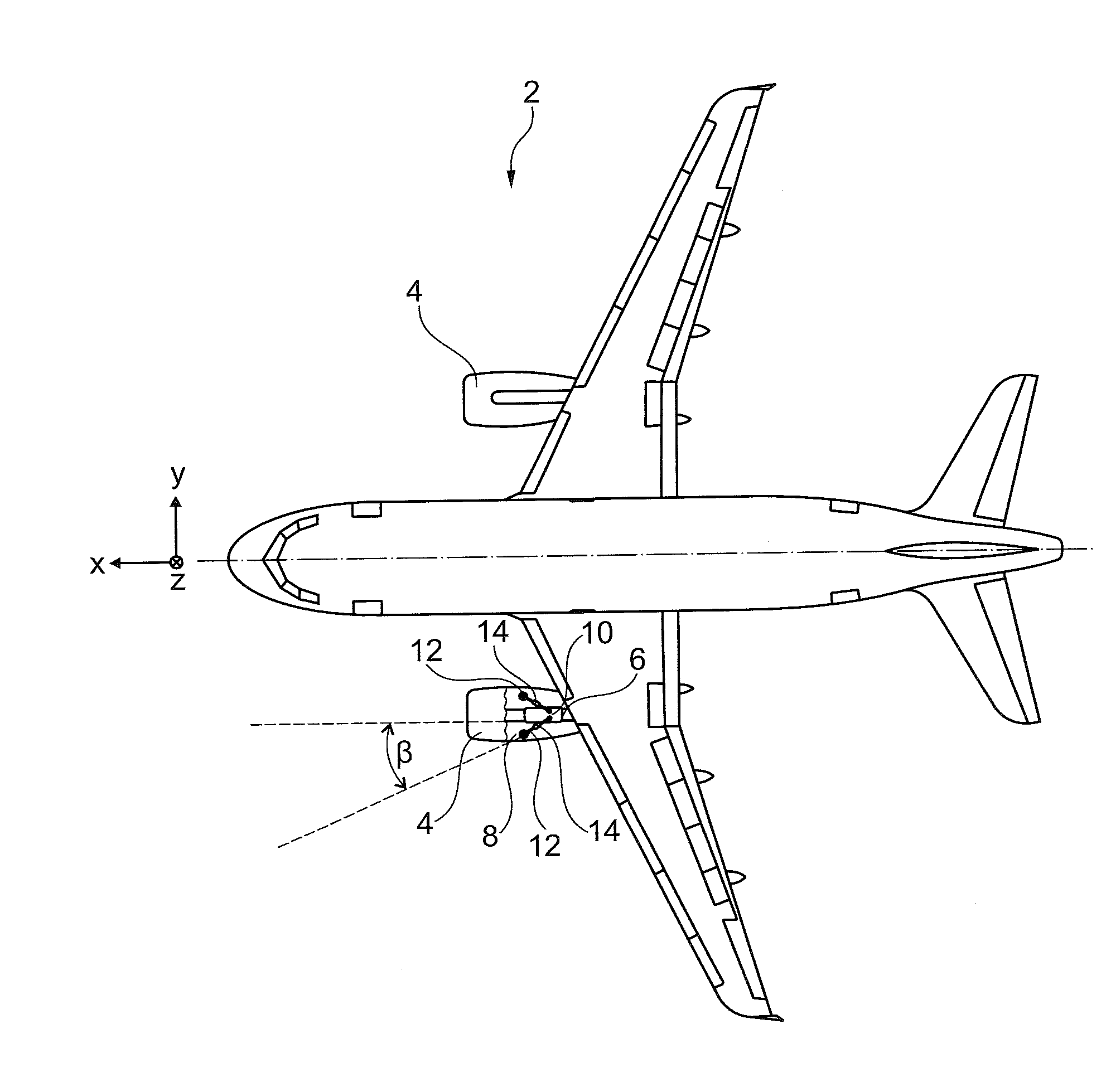
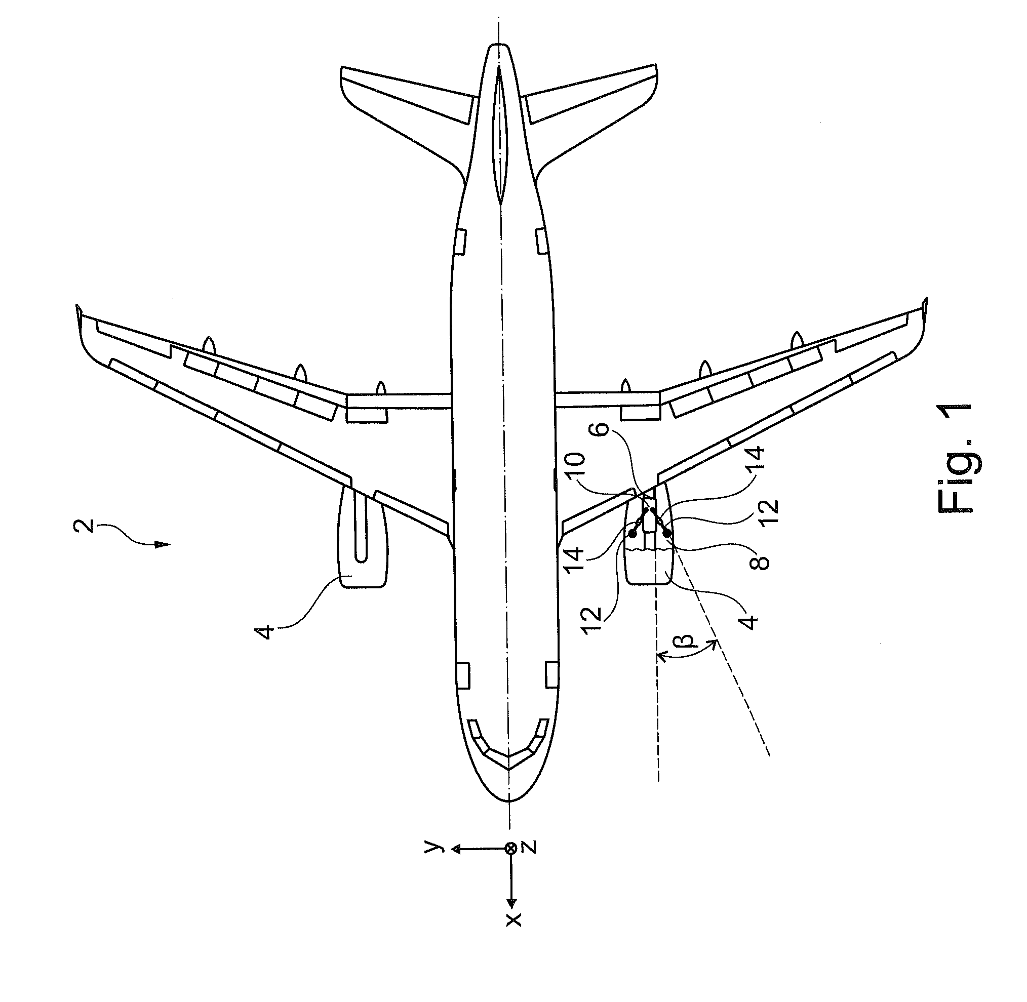
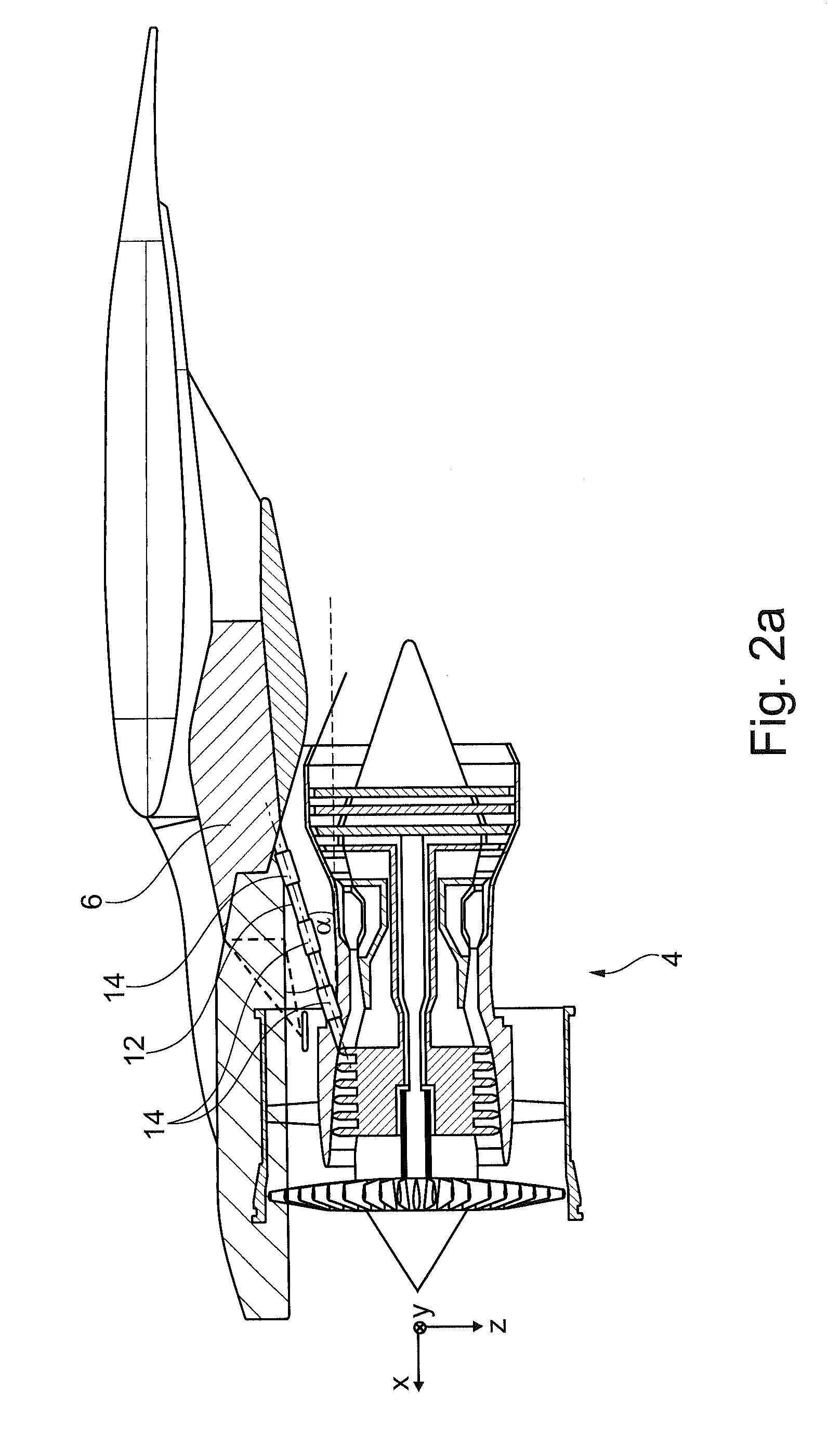
[0032]FIG. 1 shows a top view of an aircraft 2 that comprises two engines 4. Each of these engines 4 is arranged on a supporting structure 6 of the aircraft, which supporting structure 6 comprises two punctiform or flange-like bearings 8 and 10 as well as thrust elements 12. Each engine 4 generates thrust, which manifests itself as a tensile force on the supporting structure 6. The effective direction of the thrust may coincide with the longitudinal axis X of an aircraft-fixed coordinate system (for example according to DIN 9300). The thrust elements 12 are arranged in such a manner that the engines 4 exclusively or to a very large extent introduce their thrust by way of the thrust elements 12 into the structure of the aircraft 2. Due to a non-rigid connection of the thrust elements 12 on the supporting structure 6 the thrust elements are practically exclusively subjected to tensile force.

[0033]On each thrust element 12 at least one strain gage 14 is arranged that acquires the elong...


PUM

PropertyMeasurementUnit
thrustaaaaaaaaaa
elongationaaaaaaaaaa
elongations of a pluralityaaaaaaaaaa

Abstract

A method for determining the thrust of at least one engine, which is held on a supporting structure of a vehicle, includes the steps of acquiring the elongation of at least one structural element onto which the thrust of the at least one engine acts, by means of at least one strain gage; calculating the force causing the elongation in the at least one structural element, taking into account the materials characteristics of the structural element; and determining the thrust of the at least one engine as an effective force component in the direction of thrust of the vehicle. It is thus not necessary to carry out an estimate of the thrust on the basis of other physical variables such as shaft speeds, pressure or exhaust gas temperature of engines.

Description

CROSS-REFERENCE TO RELATED APPLICATIONS[0001]This application claims the benefit of the filing date of U.S. Provisional Patent Application No. 61 / 551,538, filed Oct. 26, 2011, the disclosure of which is hereby incorporated herein by reference.TECHNICAL FIELD[0002]The invention relates to a method and an apparatus for determining the thrust of an engine on a vehicle, and to an aircraft comprising at least one engine and an arrangement for determining the thrust of the at least one engine.BACKGROUND TO THE INVENTION[0003]At present, the thrust provided by means of engines on an aircraft is not displayed as such in a cockpit. Instead, in the cockpit various measured physical parameters are presented from which a pilot can estimate the corresponding thrust. Depending on the manufacturer of the engine, the parameters may comprise the current pressure ratio, the exhaust temperature, the rotational speed of a low-pressure shaft, the rotational speed of a high-pressure shaft, and the fuel m...

Claims


Application Information

Patent Timeline
Patent Type & Authority Applications(United States)
IPC IPC(8): G01L1/00
CPCG01L1/00G01L5/133B64D31/00B64D43/00B64D2027/268
Inventor HEGENBART, MATTHIASSOMDA, NABANKELE-MARTIAL
Owner AIRBUS OPERATIONS GMBH
Why Eureka
Try Eureka