System and method for controlling and diagnosing a combined cycle power plant

a combined cycle and power plant technology, applied in process and machine control, instruments, nuclear elements, etc., can solve the problems of existing systems not considering the interrelationship between gas turbine and steam turbine or the overall plant operation

Active Publication Date: 2013-11-21
GENERAL ELECTRIC CO
View PDF6 Cites 9 Cited by
  • Summary
  • Abstract
  • Description
  • Claims
  • Application Information

AI Technical Summary

Benefits of technology

[0003]According to one aspect of the invention, a system in a combined cycle plant includes a measurement device configured to measure one or more parameters of plant subsystems, the plant subsystems including a gas turbine and a steam turbine; and a model processor configured to execute a model of plant performance based on the one or more measured parameters, the model processor considering an interconnection between outputs of the gas turbine and the steam turbine of the combined cycle plant.
[0004]According to another aspect of the invention, a method of controlling performance of a combined cycle power plant includes measuring one or more parameters of plant subsystems, the plant subsystems including a gas turbine and a steam turbine; modeling plant performance based on the one or more measured parameters, the modeling being based on an interconnection between outputs of the gas turbine and the steam turbine of the combined cycle power plant; determining target plant performance; and controlling one or more of the plant subsystems based on the modeled plant performance to achieve the target plant performance.
[0005]According to yet another aspect of the invention, a method of diagnosing subsystems of a combined cycle power plant includes measuring one or more parameters of plant subsystems, the plant subsystems including a gas turbine and a steam turbine; modeling plant performance based on the one or more measured parameters, the modeling being based on an interconnection between outputs of the gas turbine and the steam turbine of the combined cycle power plant; comparing at least one of the one or more parameters to the modeled plant performance to diagnose one or more of the plant subsystems.

Problems solved by technology

Further, existing systems do not consider the interrelationship between the gas turbine and the steam turbine or the overall plant operations in assessing problems or in maintaining subsystems.

Method used


Image

  • System and method for controlling and diagnosing a combined cycle power plant
  • System and method for controlling and diagnosing a combined cycle power plant
  • System and method for controlling and diagnosing a combined cycle power plant

Examples


Embodiment Construction

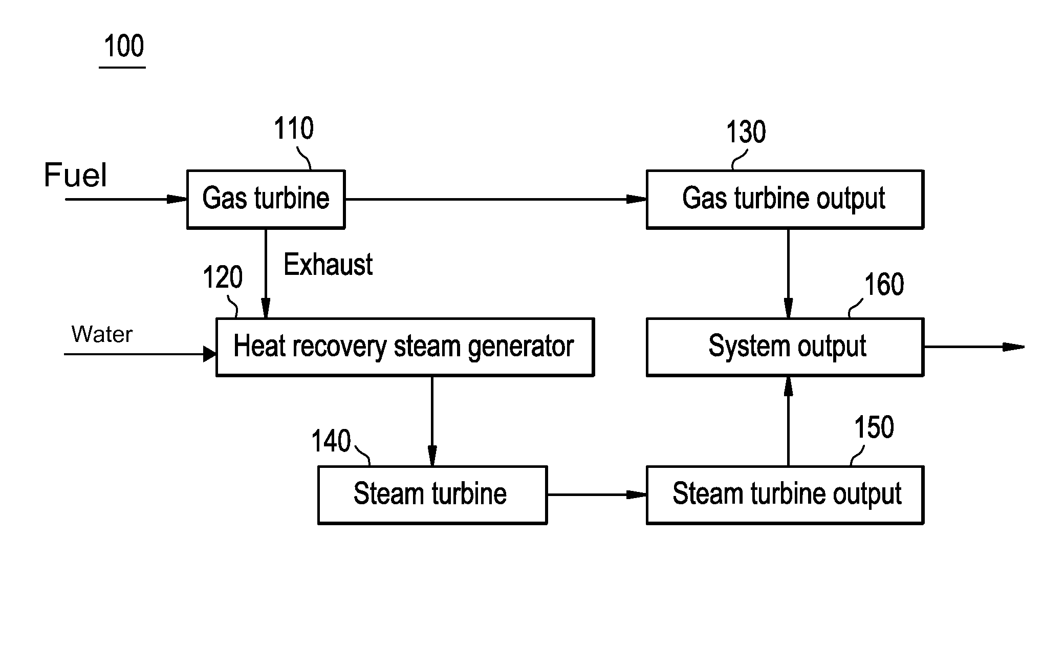
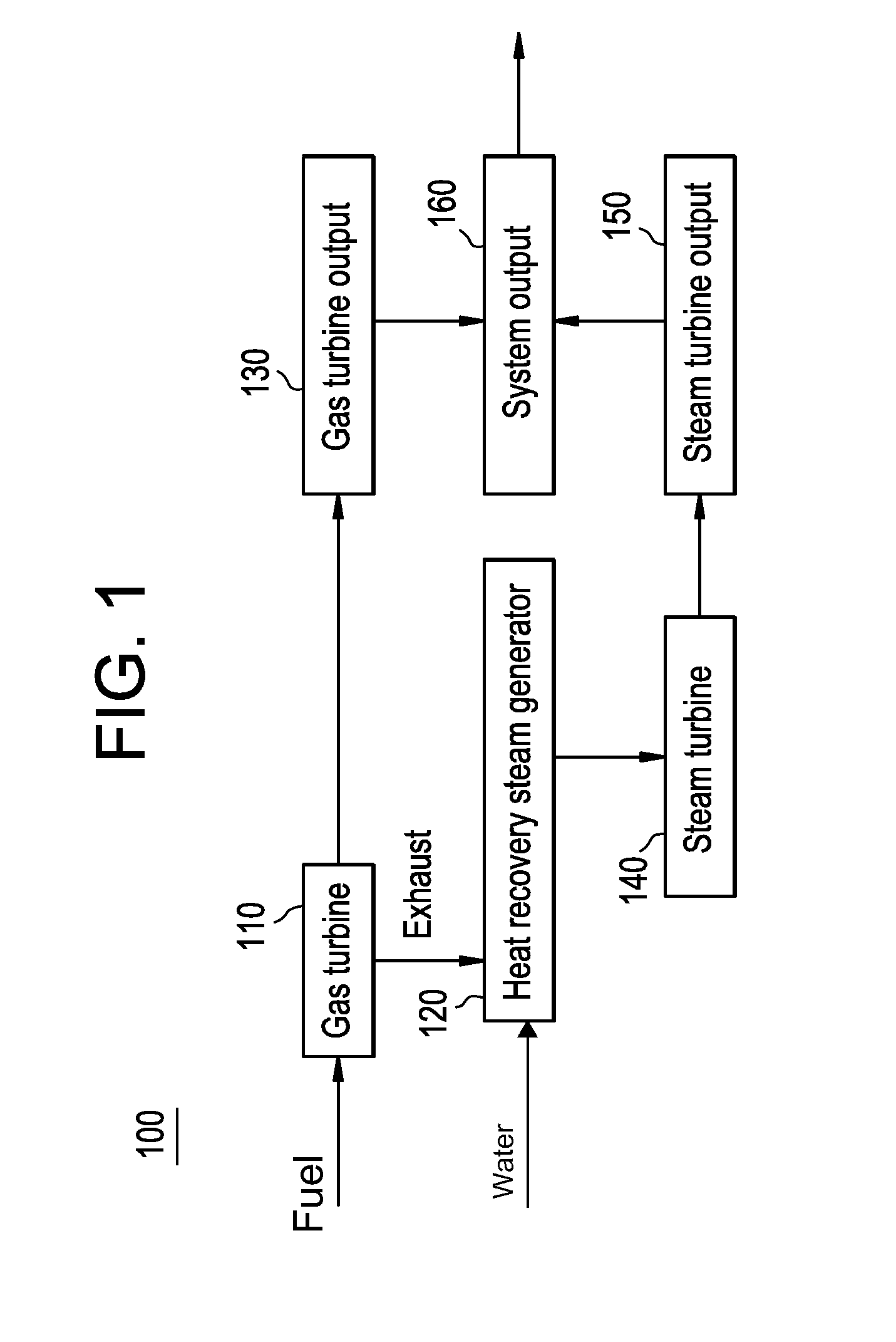
[0011]FIG. 1 is a block diagram of a combined cycle power plant 100. The combined cycle power plant 100 includes a gas turbine 110 as a primary power generator with a gas turbine output 130. The combined cycle power plant 100 also includes a steam turbine 140, which uses steam generated by a heat recovery steam generator (HRSG) 120 from the exhaust (waste) heat of the gas turbine 110, as a secondary power generator with steam turbine output 150. Thus, the ultimate system output 160 of the combined cycle power plant 100 includes both the gas turbine output 130 and the steam turbine output 150.

[0012]As opposed to simply being two independent sources of the system output 160, the gas turbine 110 and the steam turbine 140 are interrelated. That is, any change in the operation of the gas turbine 110 has both a direct (on the gas turbine output 130) and indirect (through an effect on the steam turbine output 150) effect on the system output 160. The indirect effect results from the fact t...


PUM


Abstract

A system and method in a combined cycle power plant includes a processor modeling plant level performance by considering the interrelation between outputs of the gas turbine and the steam turbine. The model can be computational, predictive, or both. The model may be used to control subsystems of the plant (including the gas turbine and the steam turbine) to achieve a target plant performance. The model may also be used to diagnose or maintain subsystems of the combined cycle power plant.

Description

BACKGROUND OF THE INVENTION[0001]The subject matter disclosed herein relates to the control, diagnosis, and maintenance of performance in a combined cycle power plant.BACKGROUND OF THE INVENTION[0002]A combined cycle power plant uses both gas and steam turbines to generate the total plant power output. The gas turbine may be considered the primary power source. Exhaust (waste heat) from the gas turbine is used to generate steam that powers the steam turbine, which generates additional power as a secondary source. Existing systems control operation of the gas turbine, the steam turbine, or other plant subsystems to affect plant performance without considering the interrelationship between the gas turbine and the steam turbine. Further, existing systems do not consider the interrelationship between the gas turbine and the steam turbine or the overall plant operations in assessing problems or in maintaining subsystems.BRIEF DESCRIPTION OF THE INVENTION[0003]According to one aspect of t...

Claims


Application Information

Patent Timeline
Patent Type & Authority Applications(United States)
IPC IPC(8): G06F1/26G06F15/00
CPCG05B17/02Y02E20/16
Inventor OSMUNDSEN, MARK ROBERTSEELY, WILLIAM FORRESTERSHOLES, JOHN EDWARDTILLERY, STEVEN WILLIAM
Owner GENERAL ELECTRIC CO
Why Eureka
Try Eureka