
Therapeutic Flotation Device

a flotation device and therapeutic technology, applied in the field of therapeutic flotation devices, can solve the problems of unwanted rotation(s) of the cervical spine, even affecting the rehabilitation process, so as to maintain proper alignment and balan

Inactive Publication Date: 2013-11-28
SECK NANCY
View PDF0 Cites 0 Cited by
  • Summary
  • Abstract
  • Description
  • Claims
  • Application Information

AI Technical Summary

Benefits of technology

The present invention is a flotation device used in pool-based rehabilitation practices. It consists of two opposed flotation members that are designed to rest on the sides of the user's head and help support their neck and head during the exercise. The flotation members are connected by means of connecting members positioned across the top of the user's head and across the lower back of the user's head, forming a ring that fits generally to the back and sides of the user's head during pool-based exercise. The invention also includes the option of discrete, spaced-apart anterior and posterior portions connected by means of lateral connecting members, allowing the user to use the device while floating on their back or stomach and help support the spine. The technical effects of the invention include improved alignment and balance, reduced risk of injury, and improved recovery from injury or surgery.

Problems solved by technology

A challenge arises, however, in the case of certain injuries under rehabilitation care that may require partial immobilization or enhanced support, as most of the known flotation devices provide only limited support and generally allow a wide range of motion.
Rehabilitation can even be hampered if the cervical spine freely rotates without maintaining proper alignment with respect the rest of the body; hence, pool-based programs are known to even employ snorkel gear to enable the head of the user to remain as still as possible keeping the neck in proper alignment to the rest of the body while performing rehabilitation exercises.
Water turbulence in the pool can even cause unwanted rotation(s) of the cervical spine, especially when the person is attempting to float and remain still.
The flotation devices are generally incapable of countering the effects of turbulence within the pool environment which may destabilize the neck and head.

Method used


Image

  • Therapeutic Flotation Device
  • Therapeutic Flotation Device
  • Therapeutic Flotation Device

Examples


Embodiment Construction

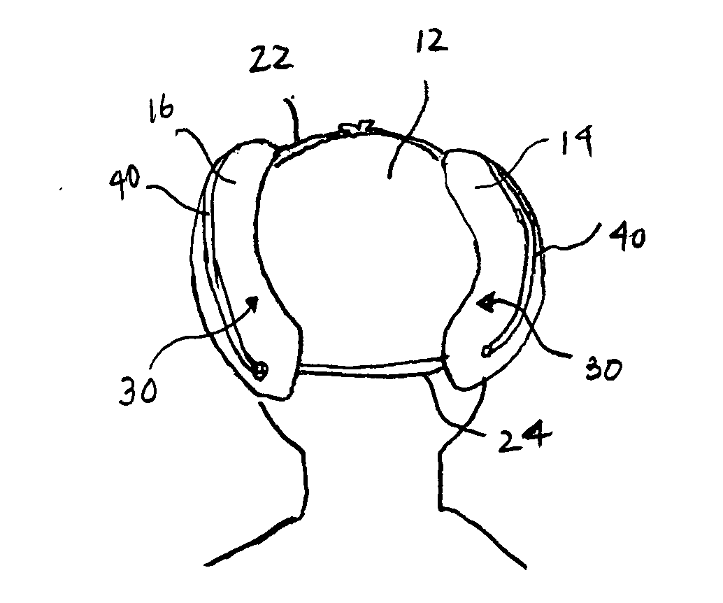
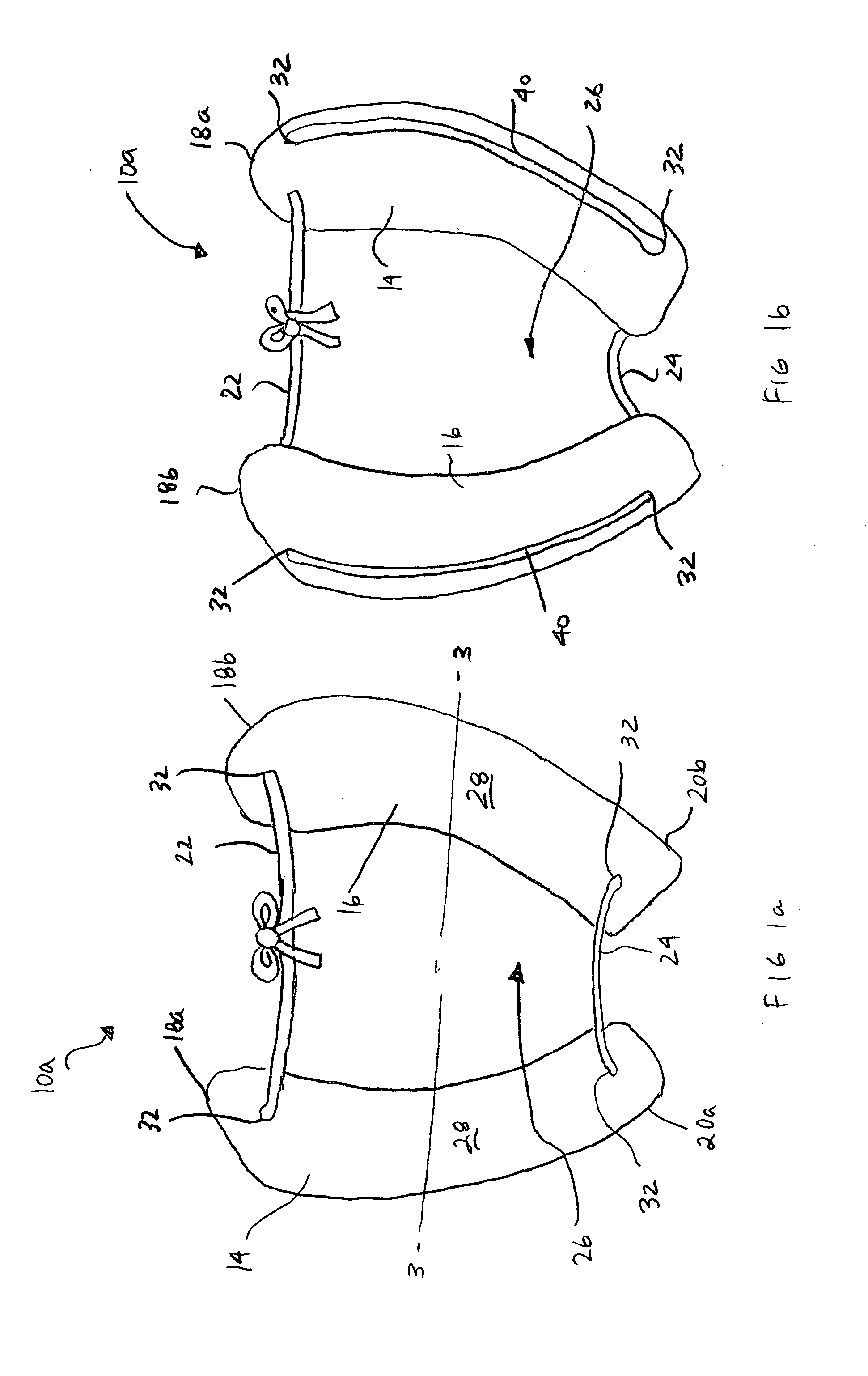
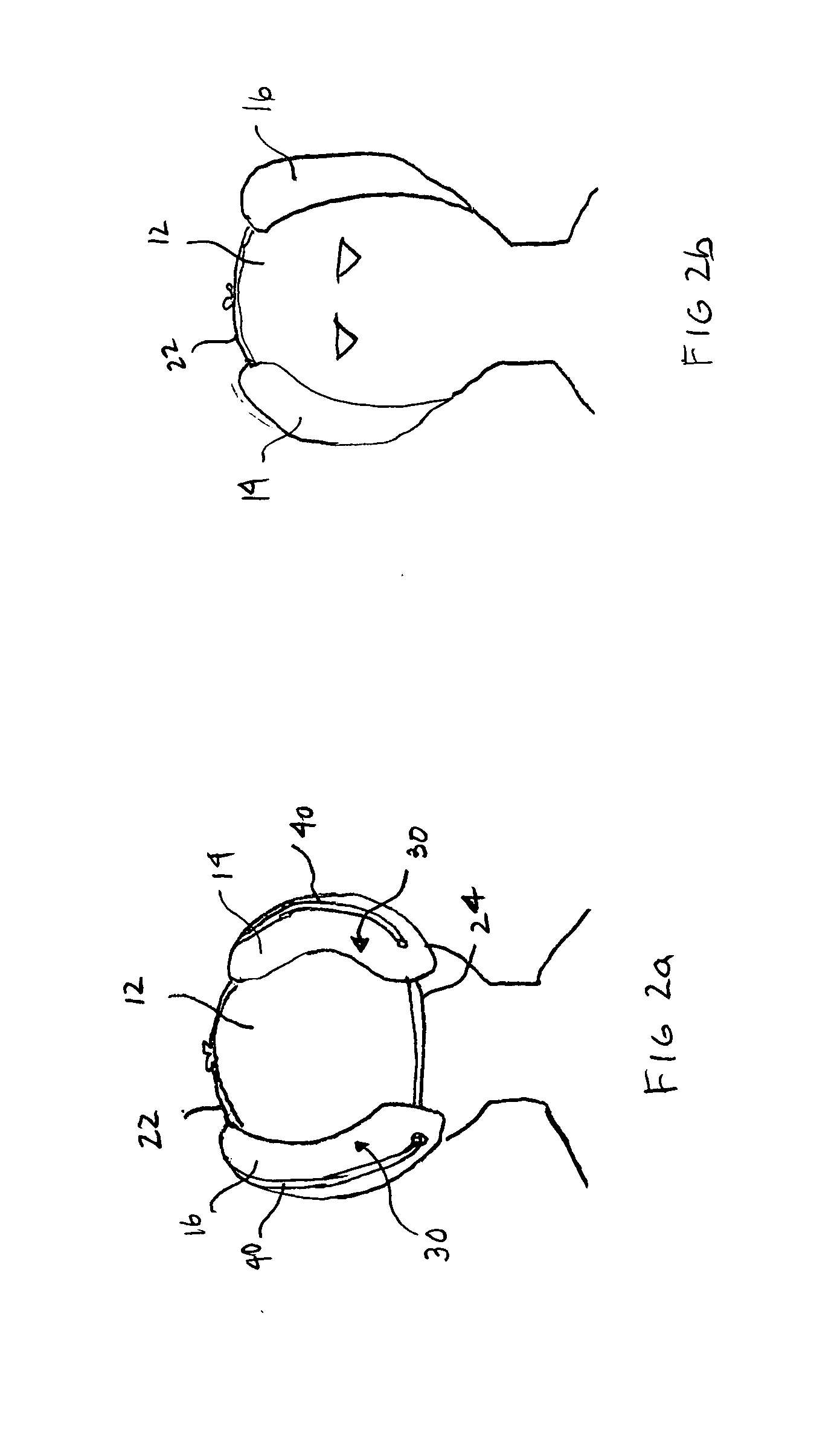
[0033]Referring to FIGS. 1a and 1b, a flotation device 10a in accordance with the present invention is illustrated. The flotation device 10a comprises a first flotation member 14 and a second flotation member 16. As can be seen in the drawings, this embodiment employs a single length of cord 40 which passes through holes 32 to bind the flotation members 14, 16 together and form the ring with which the open space 26 is defined. The cord 40 comprises the first connecting member 22 and the second connecting member 24. It will be clear to one skilled in the art that two separate cords may be used for the connecting member 22, 24 rather than a single long cord 40. In fact, the connecting members 22, 24 may, or may not be buoyant. If buoyant, the may be composed of any buoyant material or they may be air-filled or combination thereof. In addition, the connecting members may or may not be elastic as known to one skilled in the arts. The connecting member 22, 24—whether discrete elements or...


PUM


Abstract

The invention seeks to provide a therapeutic flotation device for use in a pool-based rehabilitation therapy practices for spinal rehabilitation or cervical spine rehabilitation. The flotation device comprises two opposed flotation members configured to contact the lateral sides of the user's head and support it and the neck during rehabilitation practices, which flotation members are connected to each other by means of connecting members positioned across the top of the user's head and across the lower back of the user's head. The flotation and connecting members collectively form a ring that fits generally to the back of the user's head during pool-based exercises.

Description

FIELD OF THE INVENTION[0001]The invention relates to devices for use in pool-based rehabilitation therapy practices and specifically to devices for use in spinal rehabilitation or cervical spinal rehabilitation.BACKGROUND OF THE INVENTION[0002]It is know in the art to employ various forms of flotation devices when engaged in pool-based rehabilitation therapy, specifically to support one or more parts of the body to address the particular nature of the injury or to reduce pain associated with the in-pool activities. The guiding principle, in most cases, is that the flotation device enables the body part to float in a supported position near, or at, the water surface. It is common for devices such as noodles, flotation belts, inflatable collars and buoyant platforms (such as flutter boards) to be employed for such purposes.[0003]A challenge arises, however, in the case of certain injuries under rehabilitation care that may require partial immobilization or enhanced support, as most of...

Claims


Application Information

Patent Timeline
Patent Type & Authority Applications(United States)
IPC IPC(8): A61H37/00
CPCA61H37/005B63C9/13B63C2009/133A61H2201/1604
Inventor SECK, NANCY
Owner SECK NANCY
Learn More