
Method of driving a light source, light source apparatus for performing the method and display apparatus having the light source apparatus

a technology of light source and light source, which is applied in the direction of electric variable regulation, process and machine control, instruments, etc., can solve the problems of low luminance of led, so as to improve the display quality of the display apparatus

Active Publication Date: 2013-11-28
SAMSUNG DISPLAY CO LTD
View PDF10 Cites 15 Cited by
  • Summary
  • Abstract
  • Description
  • Claims
  • Application Information

AI Technical Summary

Benefits of technology

The patent describes a method for driving a light source in a display apparatus. The method adjusts the voltage and current control parameters to keep the light source's luminance and power consumption levels uniform, regardless of local temperature conditions or driving levels. This improves the display quality of the display apparatus.

Problems solved by technology

Thus, a luminance and a power consumption of the LED may vary as local temperature varies while being driven by the constant current driving method.
Accordingly, although the LED string current might be kept constant, LED string voltage and power consumption are likely to undesirably vary as a function of local temperature.
In addition to the temperature variation problem, when an LED is just turned on, the temperature of the LED is relatively low so that the luminance of the LED is relatively high.
Accordingly, a display quality of a display apparatus may decrease due to changes in ambient temperature and / or due to changes in drive duration.

Method used


Image

  • Method of driving a light source, light source apparatus for performing the method and display apparatus having the light source apparatus
  • Method of driving a light source, light source apparatus for performing the method and display apparatus having the light source apparatus
  • Method of driving a light source, light source apparatus for performing the method and display apparatus having the light source apparatus

Examples


exemplary third embodiment

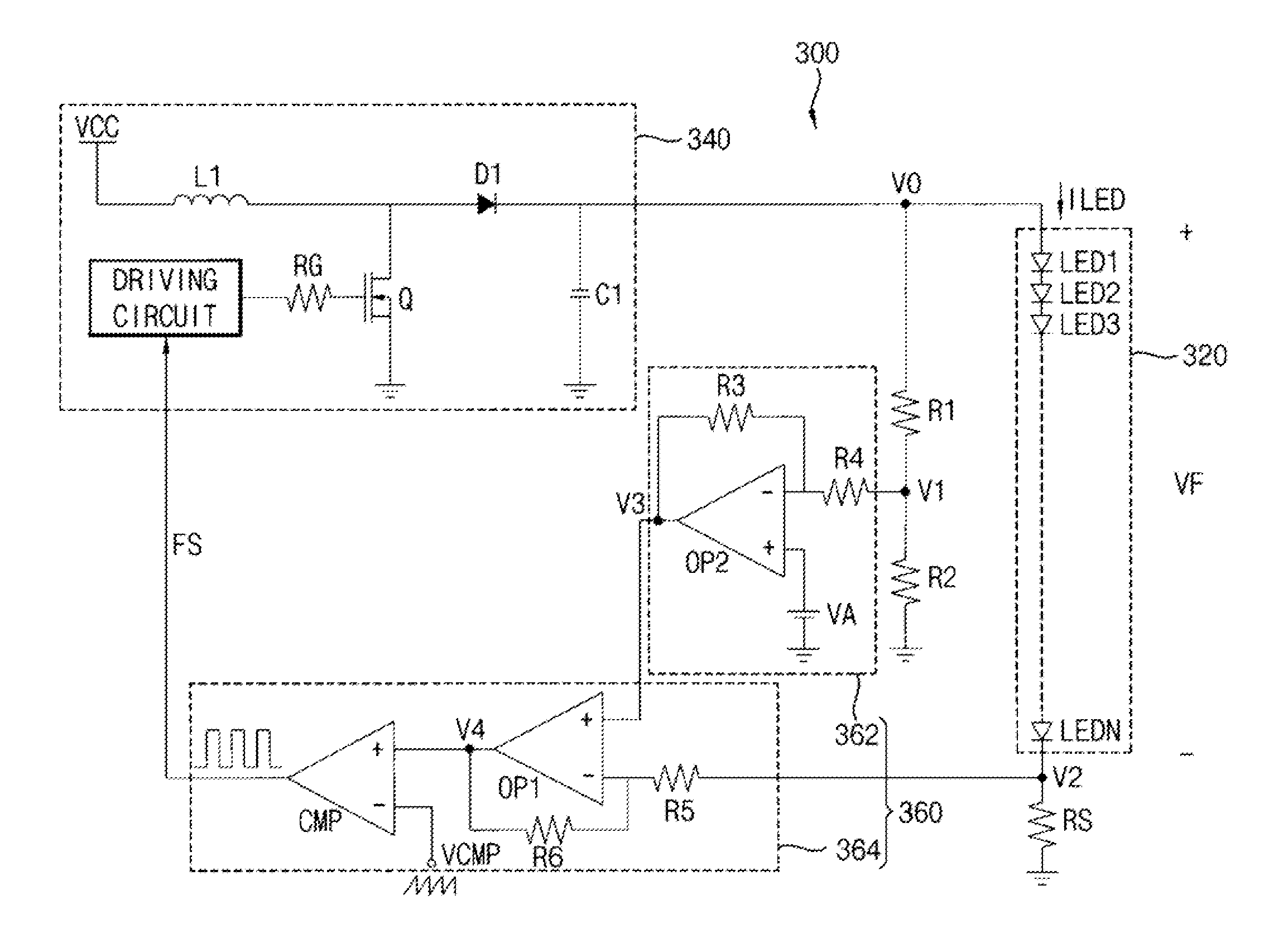
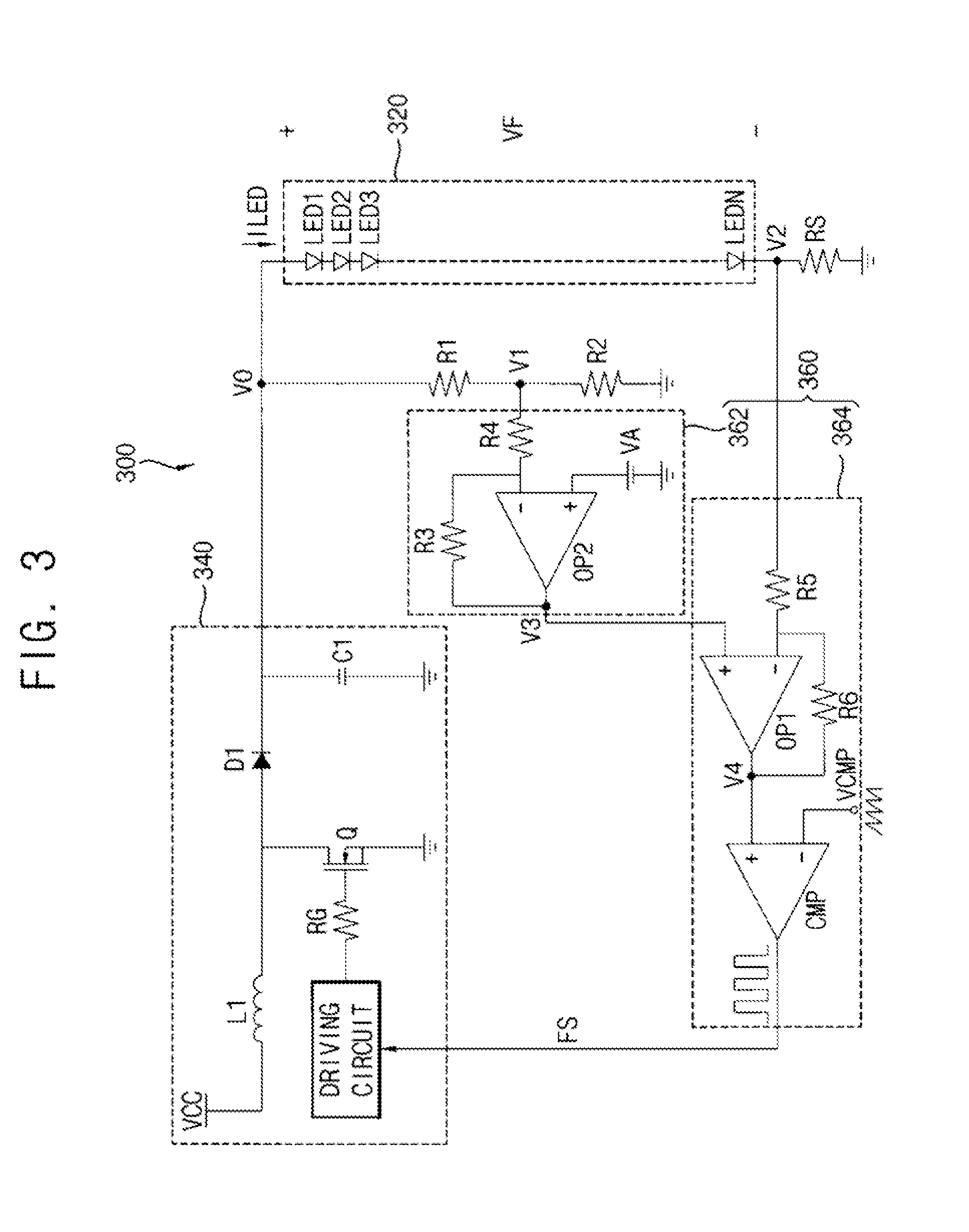
[0143]FIG. 13 is a circuit diagram illustrating a light source apparatus 300B according to the present disclosure of invention.

[0144]The light source apparatus 300B according to the present exemplary embodiment are substantially the same as the light source apparatus 300 explained referring to FIGS. 1 to 8 except for a structure of the light source part 320A which is shown to include a plurality of LED strings coupled to a currents balancing part 366. Thus, the same reference numerals will be used to refer to the same or like parts as those described in FIGS. 1 to 8 and any repetitive explanation concerning the above elements will be omitted.

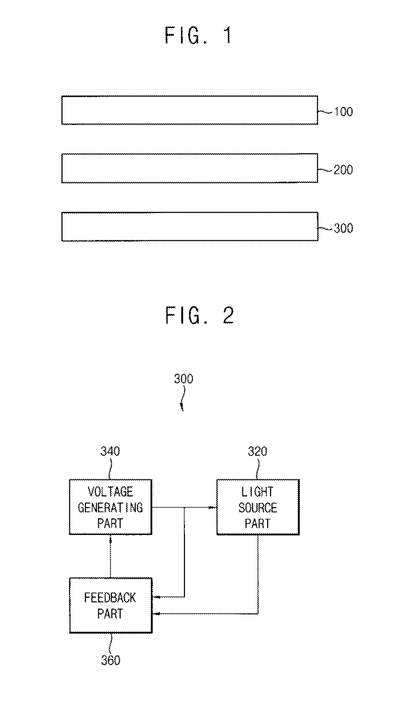
[0145]Referring to FIGS. 1, 2 and 13, the light source apparatus 300B includes a light source part 320A, a voltage generating part 340 and a feedback part 360.

[0146]The light source part 320A emits a light. The light source part 320A provides the light to the display panel 100. The light source part 320A includes a plurality of LED strings conne...


PUM


Abstract

A method of driving a light source includes outputting a variable driving voltage to a light source part, sensing a first voltage based on the driving voltage and developed at a first end of the light source part, sensing a second voltage developed at a second end of the light source part due to current passing through the light source part and adjusting the driving voltage while using the first and second voltages so that power consumption by the light source part is substantially constant irrespective of temperature of the light source part and / or irrespective of a duty cycle ration being used to drive the light source part. Thus, a luminance of the light source part may be maintained at substantially uniform levels.

Description

CROSS-REFERENCE TO RELATED APPLICATION[0001]This application claims priority to Korean Patent Application No. 10-2012-0054416, filed on May 22, 2012, and all the benefits accruing therefrom under 35 U.S.C. §119, where the contents of said application in their entirety are herein incorporated by reference.BACKGROUND[0002]1. Field of Disclosure[0003]The present disclosure of invention relates to a method of driving a light source, a light source apparatus for performing the method and a display apparatus having the light source apparatus. More particularly, the present disclosure relates to a method of driving a light source while maintaining a respective luminance and a respective power consumption of the light source respectively in substantially uniform levels.[0004]2. Description of Related Technology[0005]Generally, it is desirable to provide a liquid crystal display apparatus with a relatively small thickness, a relatively light weight and a relatively low power consumption so t...

Claims


Application Information

Patent Timeline
IPC IPC(8): H05B33/08H05B44/00
CPCH05B33/0815H05B45/3725H05B45/18G09G3/36H05B45/48H05B45/46H05B45/10H05B45/37
Inventor CHOI, MIN-SOOOH, WON-SIKSHIN, EUN-CHUL
Owner SAMSUNG DISPLAY CO LTD
Learn More