Low-power battery pack with safety system

a low-power, battery-free technology, applied in the direction of battery overheat protection, safety/protection circuit, instruments, etc., can solve the problems of battery drain, significant drain on the relatively small battery, and battery draining, etc., to achieve full gauging capability, long shelf life, and low power

Inactive Publication Date: 2013-11-28
HEARTWARE INC
View PDF1 Cites 130 Cited by
  • Summary
  • Abstract
  • Description
  • Claims
  • Application Information

AI Technical Summary

Benefits of technology

[0010]This invention results in a very low power smart battery with full gauging capability with a very long shelf life (typically, greater than 12 months). Additionally, the invention lowers the rate of device failure, despite additional hardware, by including an additional safety mechanism that will ensure that the battery monitor circuit continues to operate despite a fault that might arise from the addition of new hardware in the device.

Problems solved by technology

However, monitoring the charge of a battery generally results in the charge being depleted.
However, for a device that uses a small battery for general functioning, for example those rated at approximately 0.7 ampere-hours, the amount of power drawn by a circuit that monitors battery charge can result in a significant drain on the relatively small battery.
This problem is especially evident when the battery-powered device is not used for an extended period of time, such as when the device is being stored in inventory or shipped.
As noted above, even though a device is not being used, power is being consumed from a battery pack to continually monitor the charge, inevitably leaving the battery drained.
For devices in inventory, the need to recharge devices on a continual basis is expensive and work-intensive.
For devices being shipped, recharging may be difficult, if not impossible.

Method used


Image

  • Low-power battery pack with safety system
  • Low-power battery pack with safety system
  • Low-power battery pack with safety system

Examples


Embodiment Construction

[0015]It will be appreciated by those skilled in the art that for the sake of brevity and clarity like reference numerals may be repeated where appropriate. Additionally, specific details are set forth to provide a better understanding of the embodiments described herein. However, a skilled artisan will understand that the present invention can be practiced without the specific details, and those details may be replaced by well-known and commonly practiced equivalents. Furthermore, this written description should not be construed as being limited to the scope of the embodiments described herein.

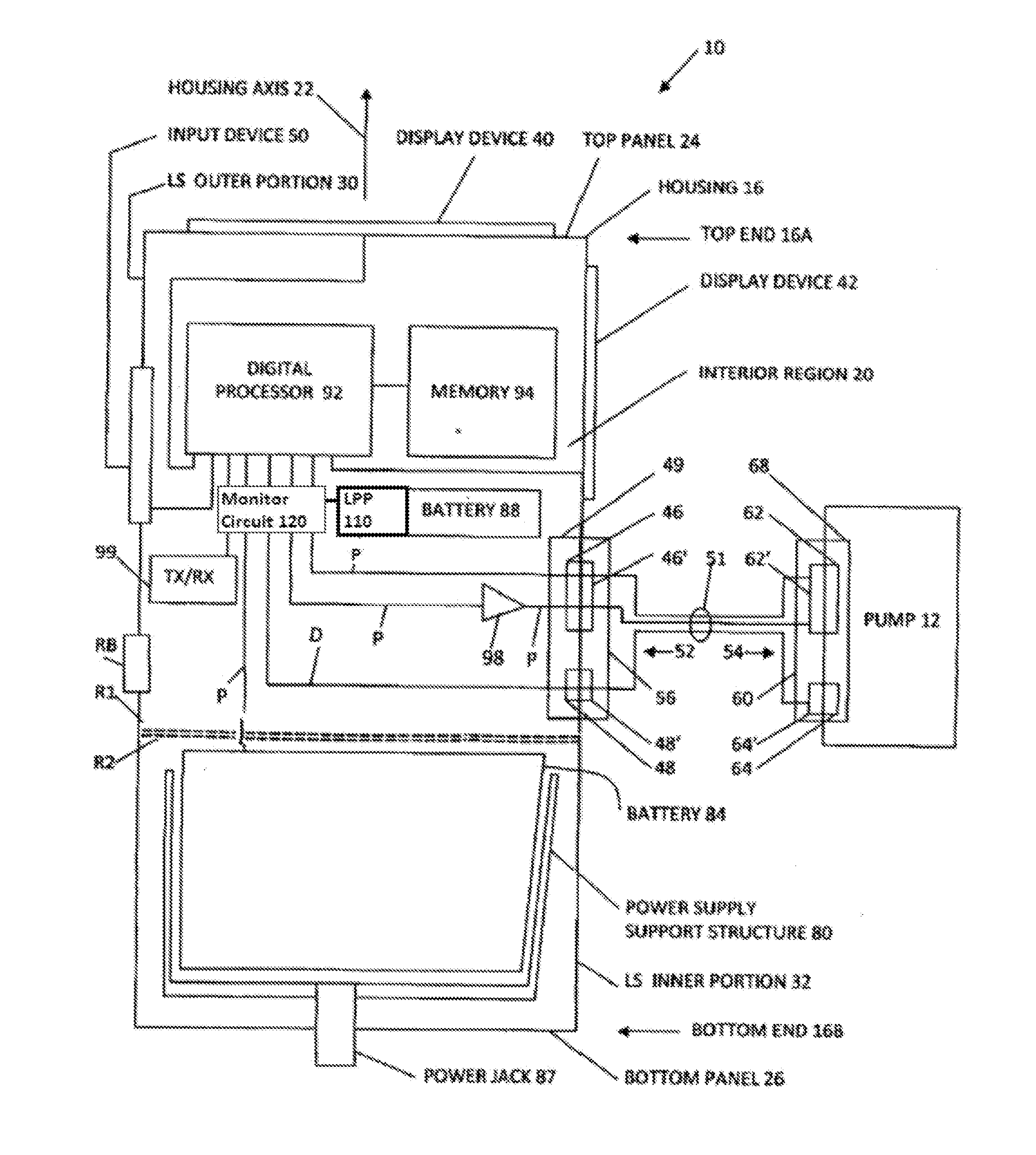
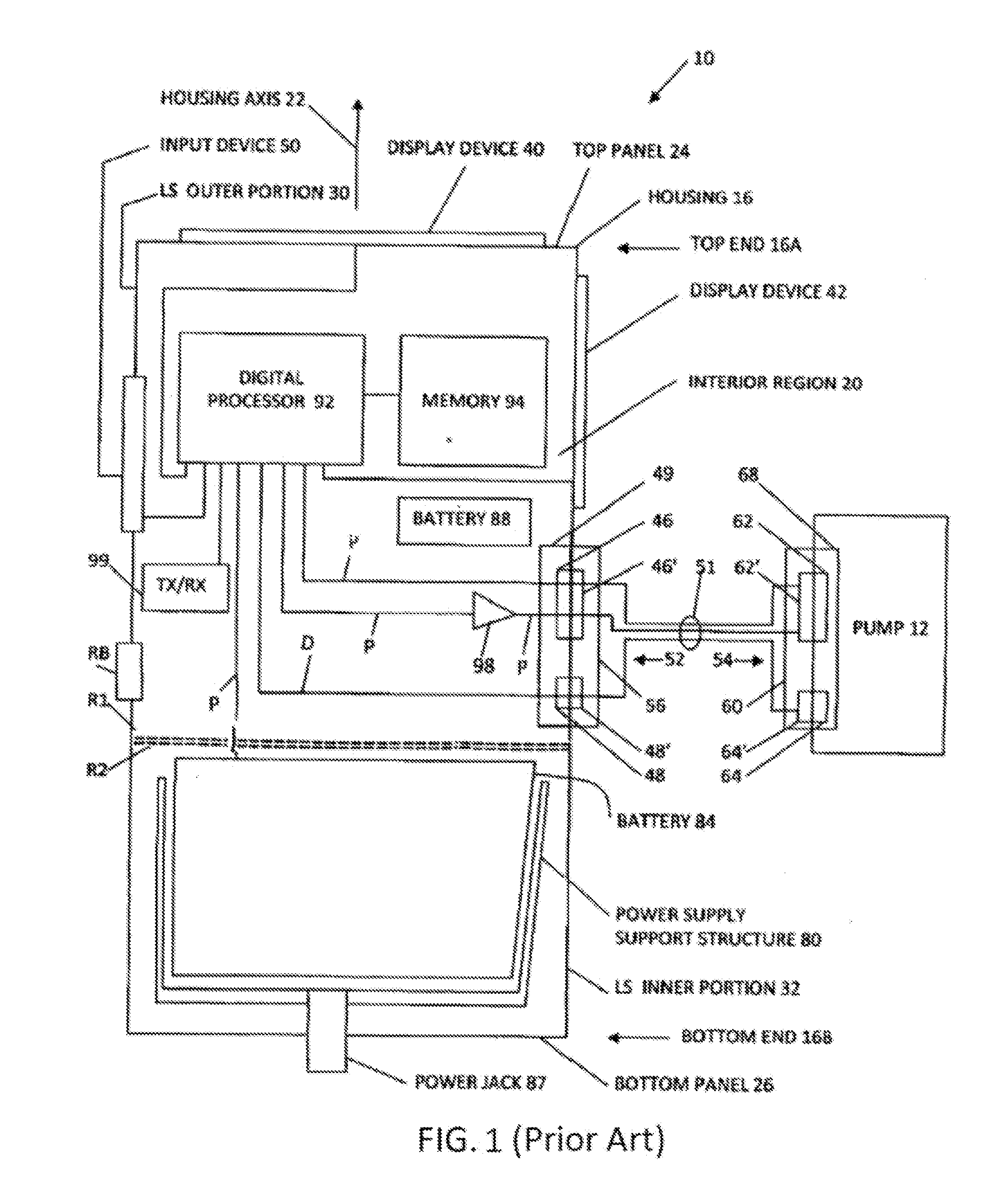
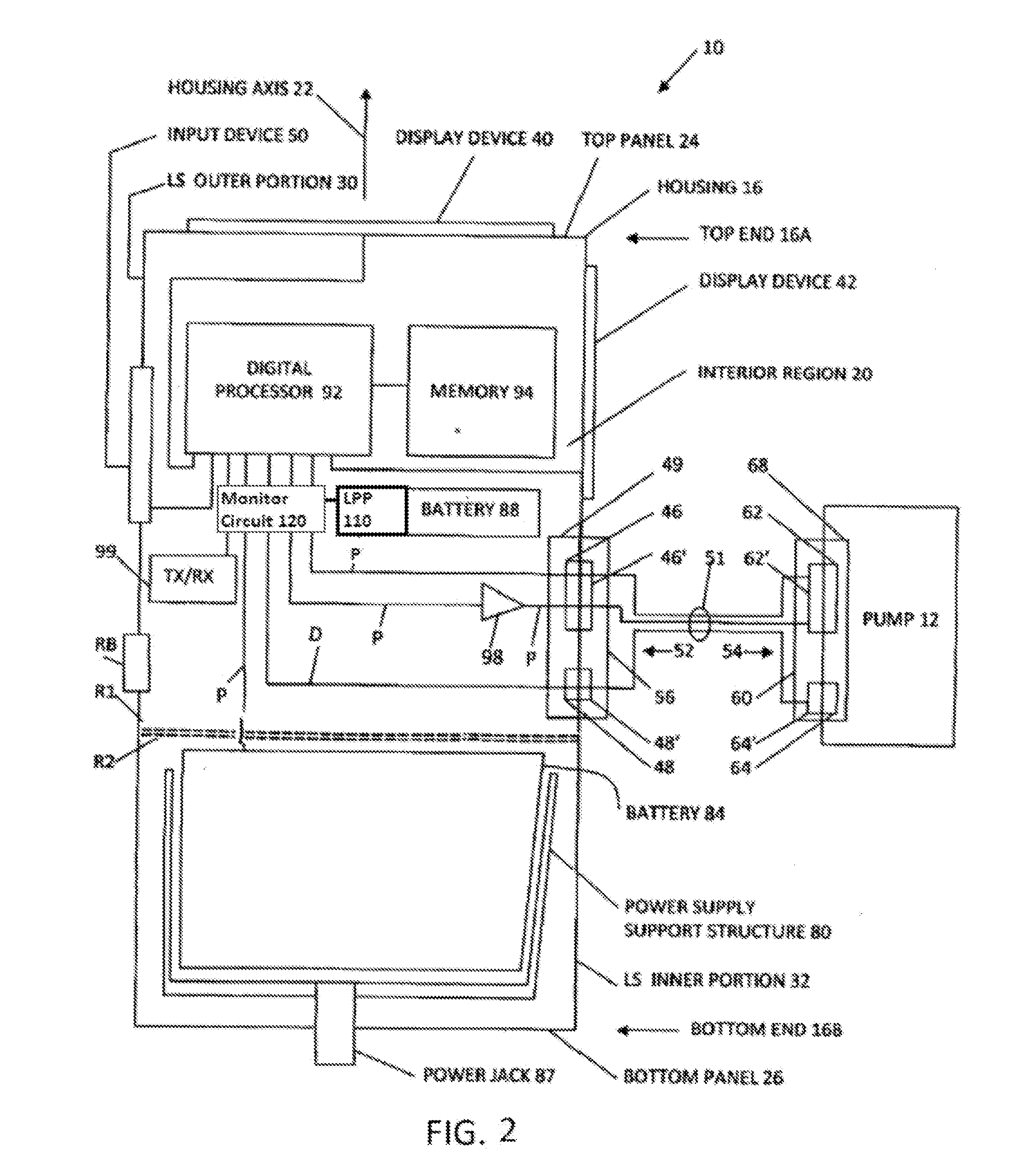
[0016]The embodiments below are discussed generally in terms of a ventricular assist system, specifically HeartWare™ Ventricular Assist System. Generally speaking, the HeartWare™ Ventricular Assist System includes a controller that is external to the patient. This external controller includes drive electronics for a pump implanted into a patient and configured to assist the heart in pumping b...


PUM


Abstract

The present application is directed toward a method and system for conserving battery power in low power systems. According to one aspect of the invention, a battery with a low power processor is used to shut off the monitor circuit that determines the charge remaining on a battery. Periodically, the low power processor will wake-up and power on the monitor circuit to determine the remaining charge of the battery. According to another aspect of the invention, there is a safety override circuit. The safety override circuit is a fail-safe that allows charge to flow from the battery when there is a fault with the low power processor, for example if the low power processor fails to wake-up.

Description

CROSS-REFERENCE TO RELATED APPLICATIONS[0001]The present application claims the benefit of the filing date of U.S. Provisional Patent Application No. 61 / 651,376 filed May 24, 2012, the disclosure of which is hereby incorporated herein by reference, and also claims the benefit of the filing date of U.S. Provisional Patent Application No. 61 / 782,358 filed Mar. 14, 2013, the disclosure of which is hereby incorporated herein by reference.BACKGROUND OF THE INVENTION[0002]This invention generally pertains to a smart rechargeable battery pack with low power processor and a safety system to help provide for an extended shelf life.[0003]Rechargeable batteries have become ubiquitous in today's world, being used in everything from cell phones and laptops to medical devices to airplanes. Often, it is desirable for a user to be kept apprised of how much charge is left in a battery powering a device. This may be especially true when devices are not used for an extended period of time, such as whe...

Claims


Application Information

Patent Timeline
Patent Type & Authority Applications(United States)
IPC IPC(8): H02J7/00
CPCH02J7/0063G06F1/3212G01R31/382H02J7/00306Y02D10/00H02J7/00308H02J7/00309H02J7/007182H02J7/0048
Inventor EAGLE, JONATHANHARDY, JON
Owner HEARTWARE INC
Why Eureka
Try Eureka