
Mixed current sensor and method for fitting said sensor

a current sensor and mixed current technology, applied in the field of mixed current sensors, can solve the problems of further problems such as the difficulty of industrializing solutions using a closed torus, and the difficulty of fitting coils on their supports, and achieve the effect of simplifying the industrialization of the latter

Active Publication Date: 2013-11-28
SCHNEIDER ELECTRIC IND SAS
View PDF40 Cites 16 Cited by
  • Summary
  • Abstract
  • Description
  • Claims
  • Application Information

AI Technical Summary

Benefits of technology

The invention provides an electric current measuring device that simplifies industrialization. The device includes a linking cassette fixed to a measuring device by clip-fastening, and a magnetic current sensor attached to the cassette. The sensor comprises a housing with inner and outer walls, and electronic acquisition means with holes for the electric pins. The device also includes clip-fastening means for securing the sensor to the case. The invention provides a method for fitting the device by fixing the linking cassette, positioning the assembly in the case, and soldering electric tracks onto the coil. The invention aims to make the device easier to manufacture and modify while maintaining accuracy in measuring electric current.

Problems solved by technology

Although they are very efficient, solutions using a closed torus remain difficult to industrialize due to the geometry of the torus.
Problems of fitting the coils on their support are furthermore encountered.

Method used


Image

  • Mixed current sensor and method for fitting said sensor
  • Mixed current sensor and method for fitting said sensor
  • Mixed current sensor and method for fitting said sensor

Examples


Embodiment Construction

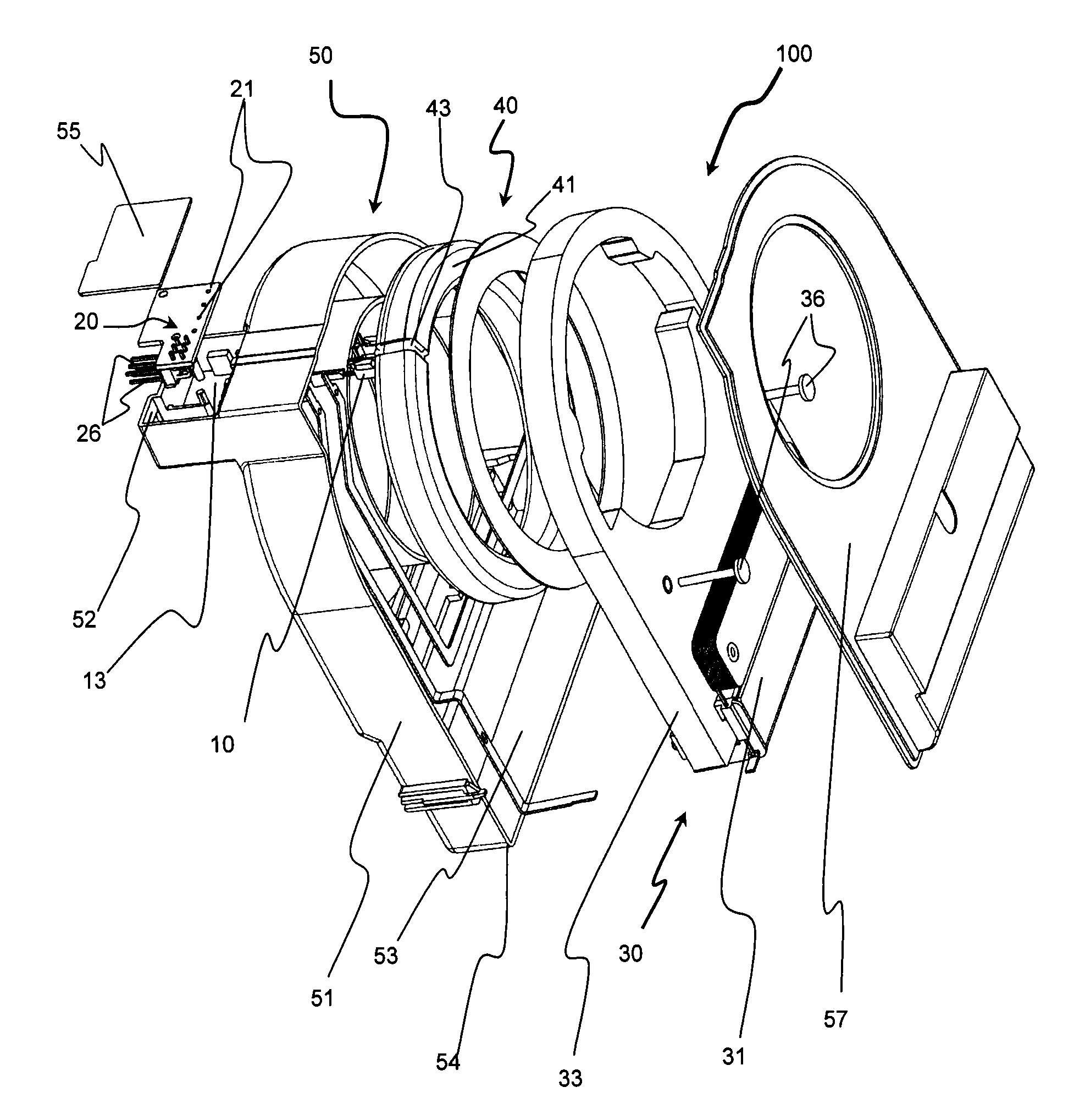
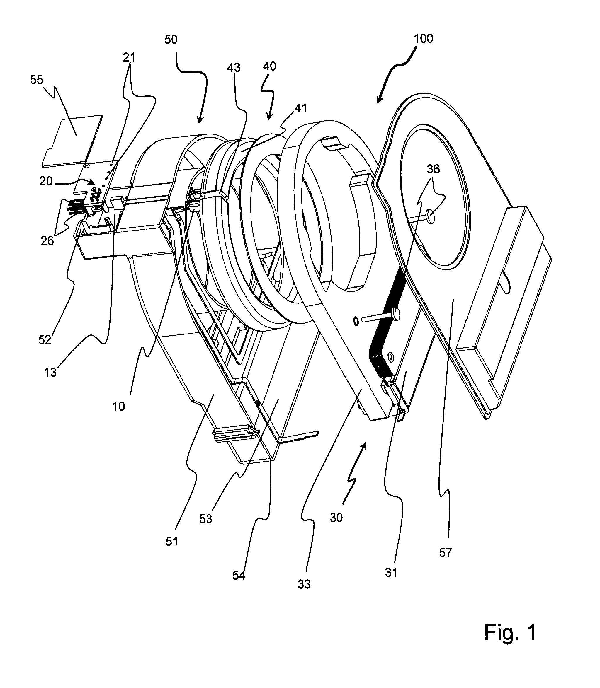
[0036]According to a preferred embodiment as represented in FIG. 1, the mixed current sensor 100 comprises a magnetic current sensor 30 and a current measuring device 40 assembled in a case 50.

[0037]The magnetic current sensor 30 comprises a coil 31 wound around a magnetic circuit 33.

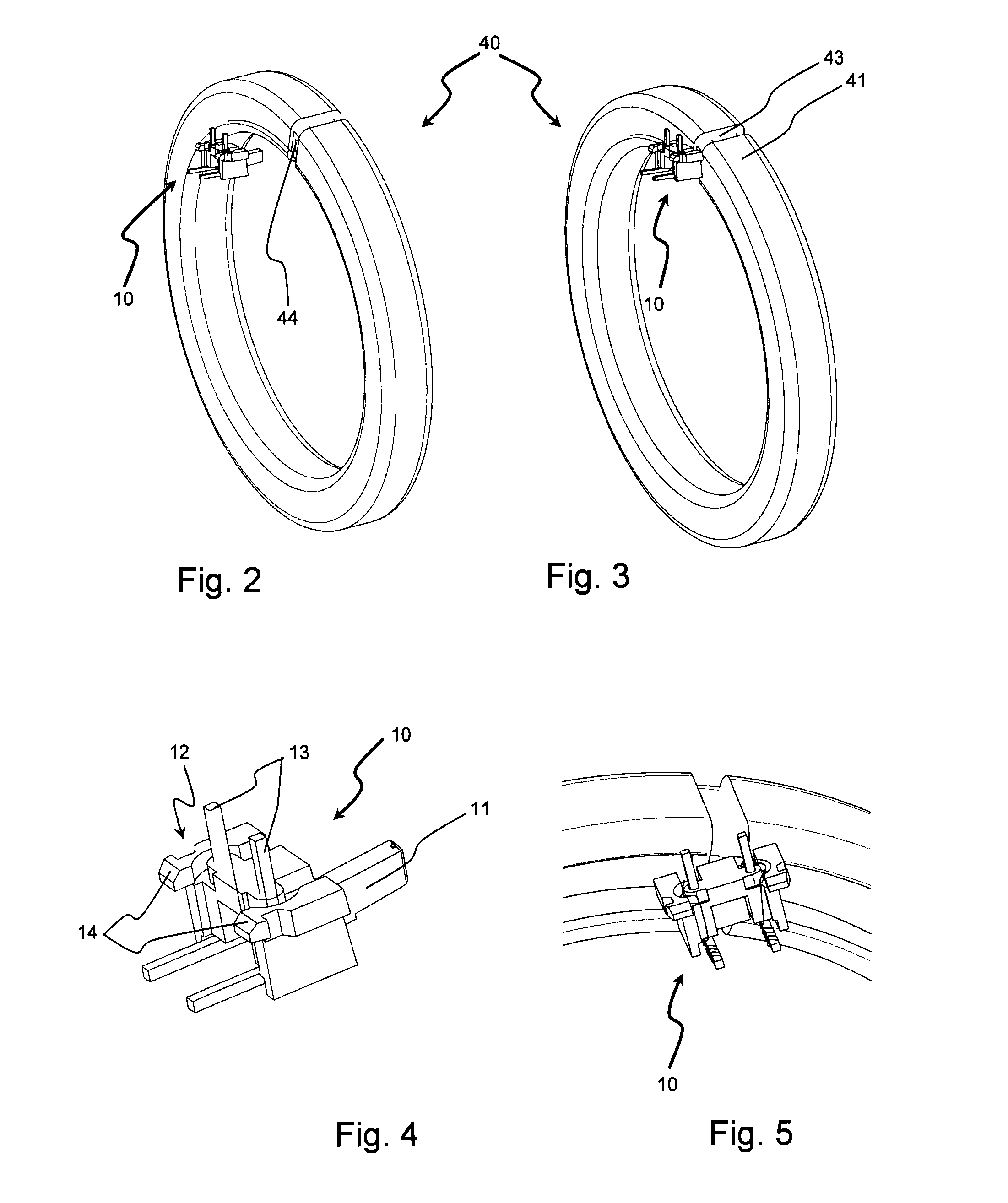
[0038]The current measuring device 40 comprises a Rogowski coil 41 arranged in such a way that a primary circuit of the magnetic sensor 30 corresponds to the primary circuit of said current measuring device 40. The Rogowski coil 41 is composed of an insulating shell 44 onto which a metal wire is wound. As an example embodiment, said shell 43 is of circular, hollow shape, made from rigid or semi-rigid non-magnetic material, preferably of cylindrical or oval cross-section. The metal wire wound onto the shell 43 is preferably made from copper or a copper-based alloy.

[0039]The case 50 is provided with a central recess 90 enabling passage of the current conductor or line 80 on which the current measurement i...


PUM

PropertyMeasurementUnit
electric currentaaaaaaaaaa
currentaaaaaaaaaa
conductingaaaaaaaaaa

Abstract

The invention relates to a mixed current sensor comprising in a case:a magnetic current sensor;a current measuring device comprising a Rogowski coil arranged in such a way that a primary circuit of the magnetic sensor corresponds to the primary circuit of said current measuring device,electronic means for performing acquisition and measurement of the electric current.Said sensor comprises a linking cassette comprisingfirst fixing means arranged to position and secure said cassette by clip-fastening onto the measuring device;second fixing means arranged to position and secure said cassette and the measuring device by clip-fastening onto the case.

Description

BACKGROUND OF THE INVENTION[0001]The invention relates to a mixed current sensor comprising in a case a magnetic current sensor having a coil wound around a magnetic circuit and a current measuring device comprising a Rogowski coil arranged in such a way that a primary circuit of the magnetic sensor corresponds to the primary circuit of said current measuring device. The mixed current sensor comprises electronic means for performing acquisition and measurement of the electric current, said means being supplied by the coil of the magnetic sensor.[0002]The invention also relates to a method for fitting the mixed current sensor.STATE OF THE ART[0003]The use of a current measuring device comprising inductive sensors of Rogowski type is extensively described in the literature.[0004]Rogowski current measurement devices comprise a support made from non-magnetic material placed around a current conductor or line in which the current to be measured is flowing. A conducting wire is wound onto...

Claims


Application Information

Patent Timeline
Patent Type & Authority Applications(United States)
IPC IPC(8): G01R19/00G01R3/00
CPCG01R19/00G01R3/00G01R15/181H01F38/30Y10T29/4913G01R15/207G01R33/02G01R33/0047G01R19/0092
Inventor LOGLISCI, DAVID
Owner SCHNEIDER ELECTRIC IND SAS
Learn More