
Sliding window for a building, home automation installation comprising such a sliding window and method for controlling the operation of a motorized drive device for such a window

a technology for sliding windows and building, which is applied in the direction of wing operation mechanisms, door/window fittings, constructions, etc., can solve the problems of high cost of obtaining sliding windows, large travel requirements, and locking of opening leaf relative to the stationary frame, and achieve the effect of simplifying the industrialization of locking control devices

Active Publication Date: 2021-03-02
SOMFY ACTIVITES SA +1
View PDF29 Cites 0 Cited by
  • Summary
  • Abstract
  • Description
  • Claims
  • Application Information

AI Technical Summary

Benefits of technology

The present invention proposes a sliding window for a building with a motorized drive device for opening and closing the window, a fittings system, and a locking control device. This arrangement simplifies the industrialization of the locking control device, ensures tightness in the closed and locked position, and minimizes costs. The window can be locked and unlocked by means of the fittings system without modifying the sealing gasket. The latch can be provided without any particular reinforcement, minimizing costs and ensuring compatibility with existing components for the fittings systems.

Problems solved by technology

However, the mechanism formed by the motorized drive device, the fittings system and the locking control device of the sliding window has the drawback of requiring ample travel to allow the movement, as well as the locking, of the opening leaf relative to the stationary frame.
Furthermore, the cost of obtaining the sliding window is high, due to the number of parts making up such a mechanism and the complexity of industrialization.
Furthermore, such a mechanism is not very esthetically pleasing due to its bulk.

Method used


Image

  • Sliding window for a building, home automation installation comprising such a sliding window and method for controlling the operation of a motorized drive device for such a window
  • Sliding window for a building, home automation installation comprising such a sliding window and method for controlling the operation of a motorized drive device for such a window
  • Sliding window for a building, home automation installation comprising such a sliding window and method for controlling the operation of a motorized drive device for such a window

Examples


first embodiment

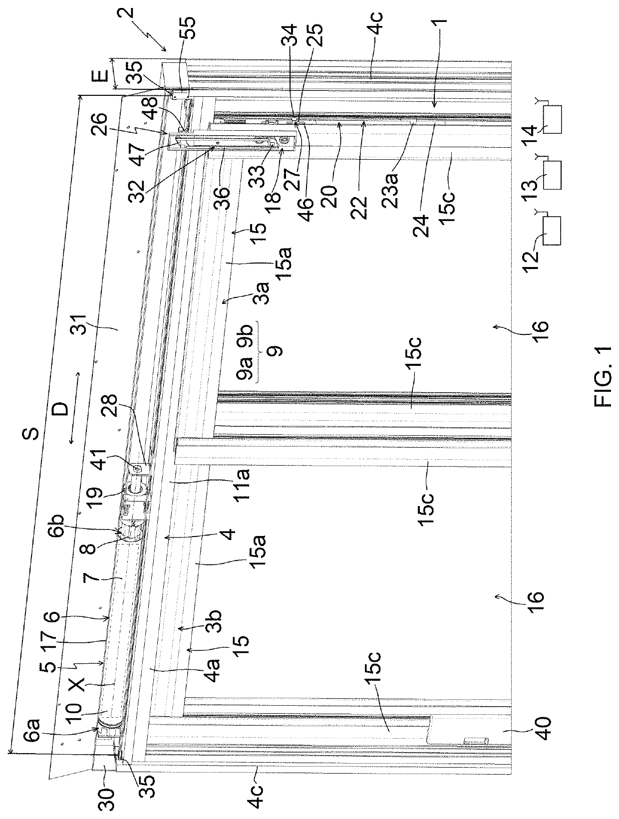
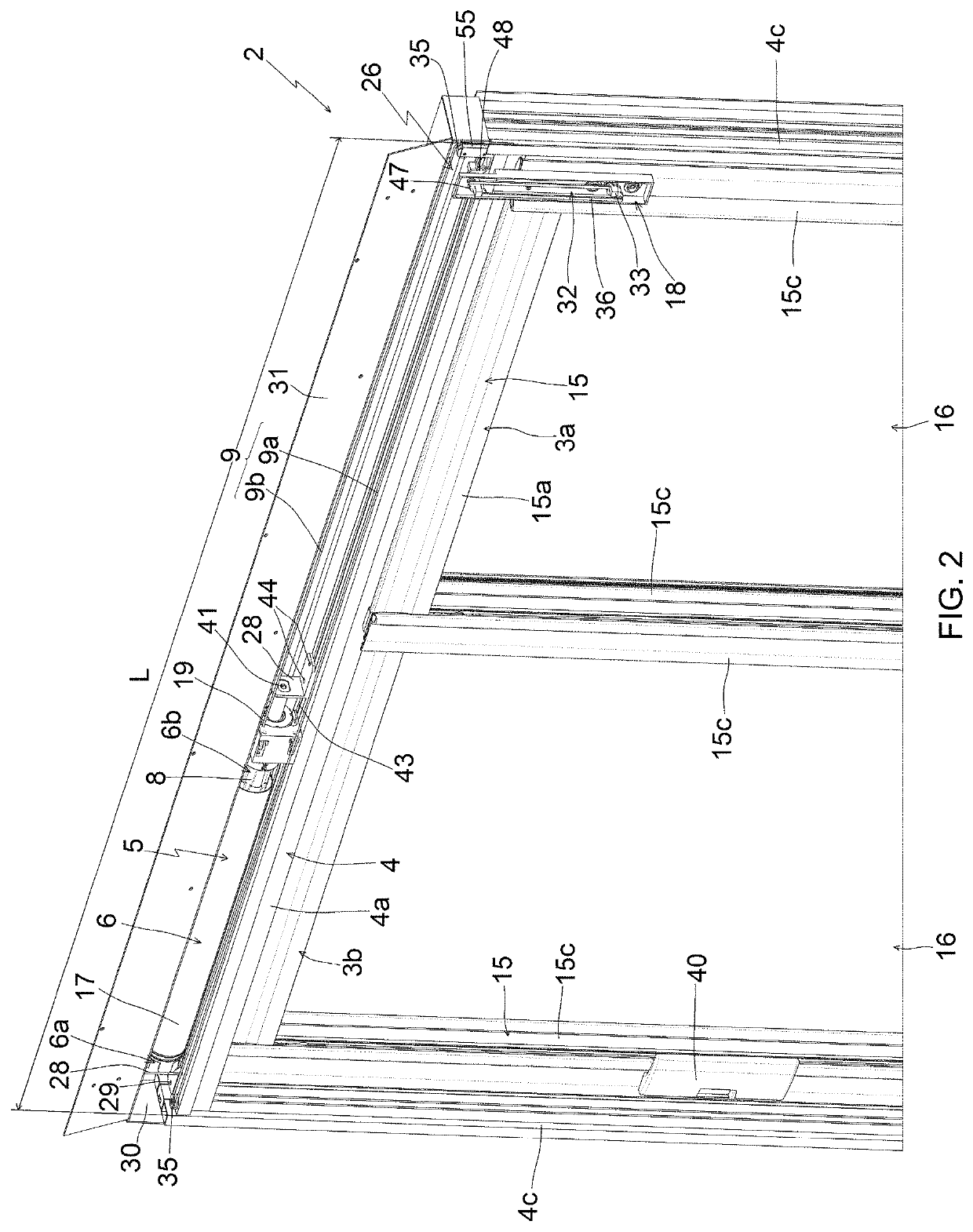
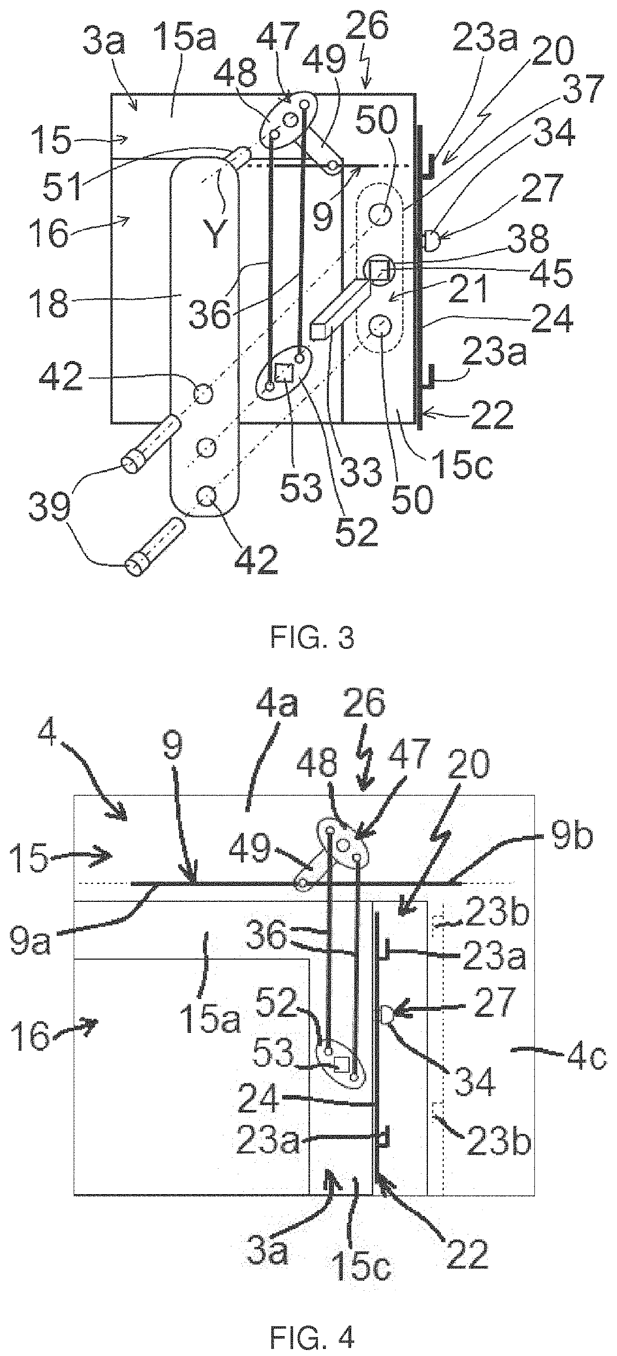
[0063]First described, in reference to FIGS. 1 to 5, is a home automation facility according to the invention and installed in a building including an opening 1, in which a sliding window 2, according to the invention, is arranged.

[0064]The sliding window 2 can also be called sliding pocket.

[0065]The present invention applies to sliding windows and sliding patio doors, which may or may not be equipped with transparent glazing.

[0066]The window 2 comprises at least one opening leaf 3a, 3b and a stationary frame 4.

[0067]Here, and as illustrated in FIGS. 1 and 2, the window 2 comprises a first opening leaf 3a and a second opening leaf 3b.

[0068]The window 2 also comprises a motorized drive device 5 for moving an opening leaf 3a by sliding relative to the stationary frame 4.

[0069]Here, the motorized drive device 5 is configured to move only one of the first and second opening leaves 3a, 3b by sliding relative to the stationary frame 4, in particular the first opening leaf 3a.

[0070]Here,...

second embodiment

[0322]In reference to FIGS. 6 to 7, we now describe the arrangement between the motorized drive device 5, the fittings system 20 and the locking control device 26, according to the

[0323]In this second embodiment, the actuating mechanism 32 of the latch 21 comprises an additional flexible element 54.

[0324]Here and as illustrated in FIGS. 6 and 7, the drive element 47 and the transmission element 52 are pulleys.

[0325]The additional flexible element 54 is configured to transmit the rotational movement from the pulley of the drive element 47 to the pulley of the transmission element 52. Furthermore, the pulley of the transmission element 52 is configured to rotate the shaft 33 of the latch 21.

[0326]In practice, the additional flexible element 54 is a cable or a cord.

[0327]It may be made from a synthetic material, for example nylon or polyethylene with a very high molar mass.

[0328]Thus, the use of an additional flexible element 54 made from a synthetic material makes it possible to minim...

third embodiment

[0344]We now describe the arrangement between the motorized drive device 5, the fittings system 20 and the locking control device 26, which is not shown.

[0345]In this third embodiment, the actuating mechanism 32 of the latch 21 comprises a gear.

[0346]Here, the drive element 47 and the transmission element 52 are pinions.

[0347]In one example embodiment, the pinion of the drive element 47 is meshed with the pinion of the transmission element 52 by means of one or several other pinions.

[0348]In a variant, the pinion of the drive element 47 is meshed directly with the pinion of the transmission element 52.

[0349]In all cases, the pinions of the elements 47 and 52 belong to a torque transmission gear, from the drive element 47 to the shaft 33, via the transmission element 52.

[0350]The gear of the actuating mechanism 32 of the latch 21 is configured to rotate the shaft 33 of the latch 21.

[0351]Advantageously, the pinion 52 also comprises the housing 53 configured to receive the shaft 33 o...


PUM


Abstract

A sliding window for a building includes a stationary frame, an opening leaf, a motorized drive device, a fittings system, and a locking control device. The motorized drive device includes an electromechanical actuator, a flexible element, and a drive arm. The flexible element drives movement of the opening leaf with respect to the stationary frame when the actuator is electrically activated. The arm is connected both to a frame of the opening leaf and to the flexible element. The locking control device collaborates with a lock of the fittings system and is actuated by the flexible element when the actuator is electrically activated. The drive arm supports the locking control device. The fittings system also includes an errorproofing system. The locking control device actuates the lock following activation of the errorproofing system and when the actuator is electrically activated.

Description

BACKGROUND OF THE INVENTIONField of the Invention[0001]The present invention relates to a sliding window for a building comprising a motorized drive device for moving an opening leaf relative to a stationary frame in a sliding movement.[0002]The present invention also relates to a home automation facility comprising such a sliding window.[0003]The present invention lastly relates to a method for controlling the operation of a motorized drive device of such a sliding window for a building.[0004]In general, the present invention relates to the field of windows comprising a motorized drive device setting an opening leaf in motion relative to a stationary frame in a sliding movement, between at least one first position and at least one second position.[0005]A motorized drive device of such a window comprises an electromechanical actuator.Description of the Related Art[0006]Already known is document EP 1,507,059 A2, which describes a sliding window for a building comprising a stationary ...

Claims


Application Information

Patent Timeline
Patent Type & Authority Patents(United States)
IPC IPC(8): E05F11/00E05F15/643E05D15/56
CPCE05F15/643E05D15/565E05Y2201/22E05Y2201/24E05Y2201/434E05Y2201/604E05Y2900/148E05Y2201/606E05Y2201/652E05Y2201/686E05Y2600/41E05Y2600/45E05Y2800/426E05Y2900/132
Inventor CAVAREC, PIERRE-EMMANUELBRECHEMIER, MARCSERVE, DAVIDJACQUIN, CHRISTOPHEBEAU, STÉPHANECRON, JULIEN
Owner SOMFY ACTIVITES SA
Learn More