Machine tool, particularly of the milling and boring type

a machine tool and type technology, applied in the field of milling and boring type, can solve the problems of reducing the precision of the coupling, requiring special labor, and complex and expensive machining to adapt the plain bearing, and achieve the effect of simple industrialization

Inactive Publication Date: 2011-02-24
HPT SINERGY
View PDF4 Cites 0 Cited by
  • Summary
  • Abstract
  • Description
  • Claims
  • Application Information

AI Technical Summary

Benefits of technology

[0022]The aim of the present invention is to provide a machine tool that obviates these drawbacks, by allowing a coupling of the boring bar in the spindle that is simple to industrialize, so as to not require complex and expensive adaptation machinings thereof.

Problems solved by technology

This entails complex and expensive machining to adapt the plain bearings, which require the use of specialized labor.
Further, one drawback of this type of machine consists of the degradation of the precision of such coupling, which is due to the progressive wear and corrosion of the plain bearings, to the full disadvantage of the quality of the operations that can be performed with such machines.
Another drawback of this type of machine is constituted by the fact that the possibility for dynamic balancing in rotation of the boring bar / spindle system is limited by the play between the boring bar and the plain bearings, which is necessary for mutual sliding.
A further drawback of this type of machine tool is that due to the thermal variations that occur during operation, the coupling play between the boring bar and the sliding bearings changes, to the full disadvantage of the centering and balancing stability of the boring bar in the spindle, with respect to the common main working axis, and to the disadvantage of the easy sliding of the spindle in the plain bearings.
Although this solution is appreciated in that it does not require extreme precisions in coupling between the boring bar-spindle element and its support, it has some drawbacks, which include causing high power dissipation due to the fluid drag opposed by the film of oil that is interposed between the bearings and the boring bar-spindle element and is entrained thereby during its rotation.
Moreover, for some machinings such as the boring of frames of hydraulic turbines, which can reach a few meters in diameter, it is necessary to use tools that have equally extensive diameters and may weight even hundreds of kilograms.
Therefore, the boring bar-spindle element currently does not have characteristics of stiffness that allow its use for machinings with very large tools.

Method used


Image

  • Machine tool, particularly of the milling and boring type
  • Machine tool, particularly of the milling and boring type
  • Machine tool, particularly of the milling and boring type

Examples


first embodiment

[0096]Conveniently, in a first embodiment, shown in particular by way of non-limiting example in FIG. 11, the third ducts 39 comprise at least one longitudinal cavity 55 formed within the thickness of the appendage 40.

second embodiment

[0097]In a second embodiment, shown in particular by way of non-limiting example in FIGS. 10 and 12, the third ducts 39 comprise an interspace 56 delimited by an internal wall 57 of the appendage 40 and by an external wall 58 of the rod 41 that is accommodated therein.

[0098]With reference to FIG. 10, in such particular embodiment advantageously there are annular plugs 59 to delimit longitudinally the interspace 56.

[0099]Further, annular spacers 60 are conveniently provided which are arranged along the interspace 56 in radial abutment against the internal wall 57 and the external wall 58.

[0100]Such radial spacers are conveniently diffusely perforated to allow the passage of fluid along the interspace 56.

[0101]Conveniently, in the first embodiment, shown in particular by way of non-limiting example in FIG. 11, the appendage 40 comprises a tubular key 61 for connection to the boring bar 13 that is inserted axially and jointly in its first end 23.

[0102]FIG. 11 shows that the tubular key...

third embodiment

[0105]In a third embodiment, not shown in the accompanying drawings, such appendage conveniently is monolithic with the boring bar.

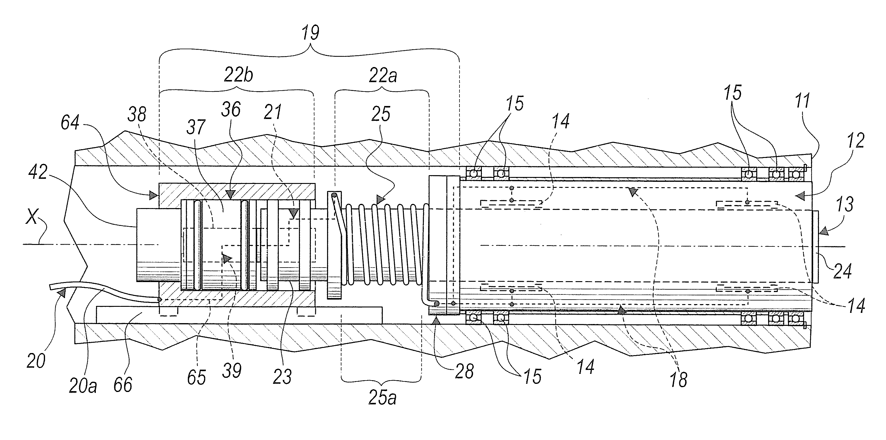
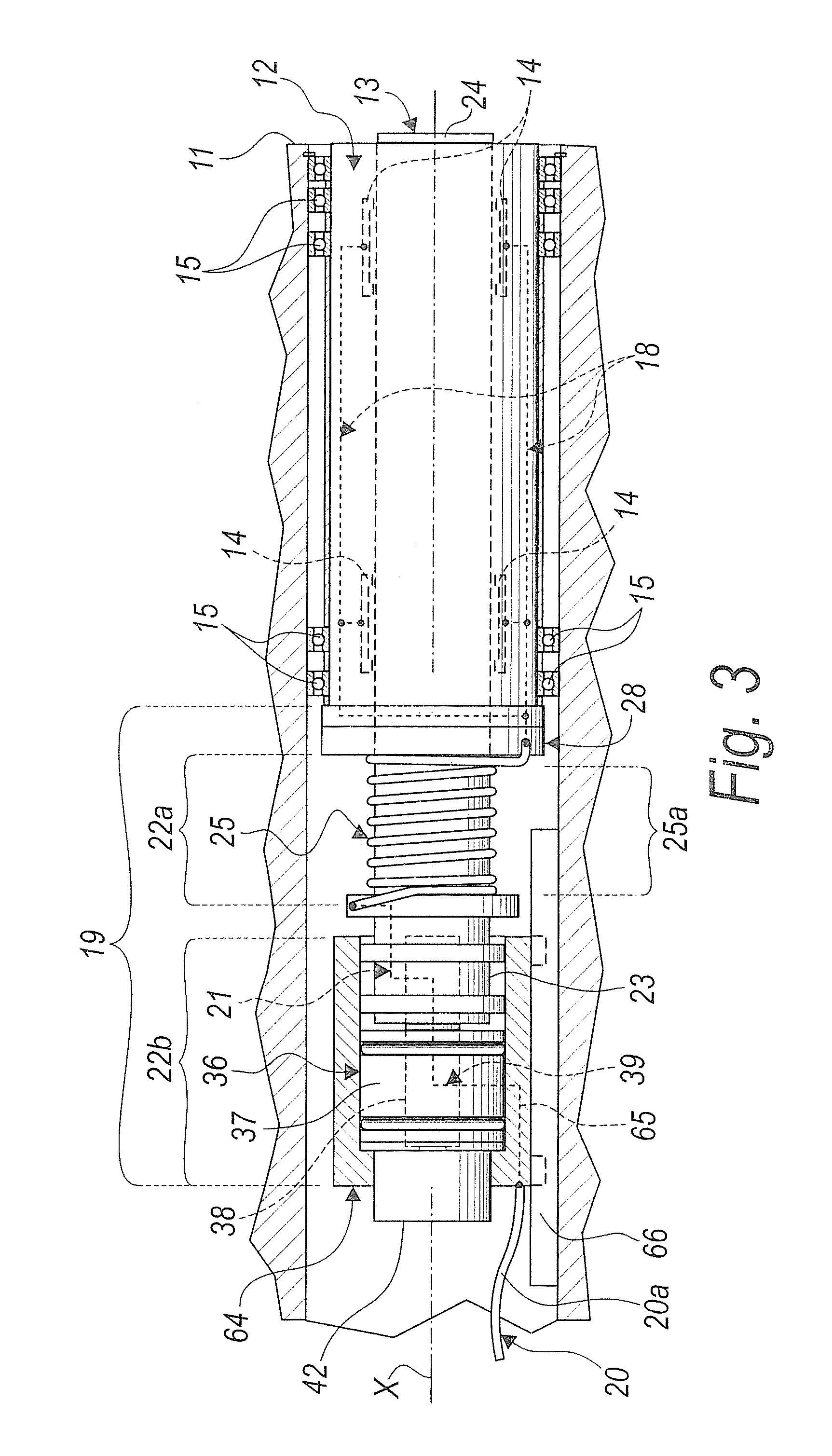
[0106]The second connection means 22b preferably comprise a supporting slider 64 for the annular element 46, the third ducts 39 advantageously comprising at least one connecting duct 65 that passes through the slider 64.

[0107]Moreover, conveniently there is a guide 66 that is associated with the support 11 and supports the slider 64 so that it can slide along the main axis X, jointly with the boring bar 13.

[0108]Advantageously, the distribution unit 20 comprises a first component that is fixed to the support 11 and a second component that is connected to the first component and can be adapted to the position of the slider 64 during the operation of the machine.

[0109]Such second component conveniently comprises a flexible distribution hose 20a, which is supported for example by a guiding chain, not shown in the accompanying figures, which controls its pos...


PUM

PropertyMeasurementUnit
transmissionaaaaaaaaaa
elastic deformationaaaaaaaaaa
diameteraaaaaaaaaa

Abstract

A machine tool, particularly of the milling and boring type, comprising:
    • a support for a spindle that accommodates coaxially a boring bar that is connected thereto by means of hydrostatically supported bearings,
    • elements for the joint rotation of the spindle and of the boring bar about a main machining axis,
    • elements for the translational motion of the boring bar with respect to the spindle along the main axis.
First ducts for feeding fluid to the hydrostatically supported bearings are provided through the spindle. The boring bar has elements for transmitting the fluid from a provided distribution unit, which is substantially fixed to the support, to the first ducts, which rotate with the spindle.

Description

[0001]The present invention relates to a machine tool particularly of the milling and boring type.BACKGROUND OF THE INVENTION[0002]Milling and boring machine tools are currently known which comprise:[0003]a support for a spindle that accommodates coaxially a boring bar that can slide therein,[0004]means for joint rotation of the spindle and of the boring bar about a main working axis,[0005]means for the translational motion of the boring bar with respect to the spindle along the main axis.[0006]A first model of this type of machine has the spindle connected to the support by means of radial and axial rolling bearings and accommodates the boring bar, which can slide therein on plain bearings.[0007]This type of machine tool has a motor for the joint rotation of the spindle and of the boring bar and a motor for the sliding of the boring bar in the spindle.[0008]In order to ensure reliability and precision of the machining performed, the need is felt for a coupling between the boring ba...

Claims


Application Information

Patent Timeline
Patent Type & Authority Applications(United States)
IPC IPC(8): B23Q1/38B23Q11/12
CPCB23Q1/0027B23Q1/38Y10T409/303976B23Q5/32B23Q1/4828
Inventor GUELI, FRANCESCO
Owner HPT SINERGY
Why Eureka
Try Eureka