Portable communication apparatus

a communication device and portable technology, applied in the direction of simultaneous aerial operations, antenna details, antennas, etc., can solve the problems of poor communication quality, large whole circuit size of antennas, more restrictions, etc., and achieve the effect of improving design reliability, improving communication quality, and maximizing circuit space utilization

Active Publication Date: 2013-11-28
TCL CHINA STAR OPTOELECTRONICS TECH CO LTD
View PDF2 Cites 7 Cited by
  • Summary
  • Abstract
  • Description
  • Claims
  • Application Information

AI Technical Summary

Benefits of technology

[0005]Therefore, one of the objectives of the present invention is to provide a portable communication apparatus which can solve the above-mentioned problems.
[0007]According to the above-described embodiment, the advantages of better space utilization for circuit design, higher design reliability for the portable communication apparatus, and improved communication quality can be easily achieved.

Problems solved by technology

This higher correlation coefficient causes the whole circuit size of antennas to become very large.
A very large circuit size for antenna implementation will cause more restrictions when implementing other appliances of a traditional portable communication apparatus.
In addition, the higher correlation coefficient also results in poor communication quality.

Method used


Image

  • Portable communication apparatus
  • Portable communication apparatus
  • Portable communication apparatus

Examples


first embodiment

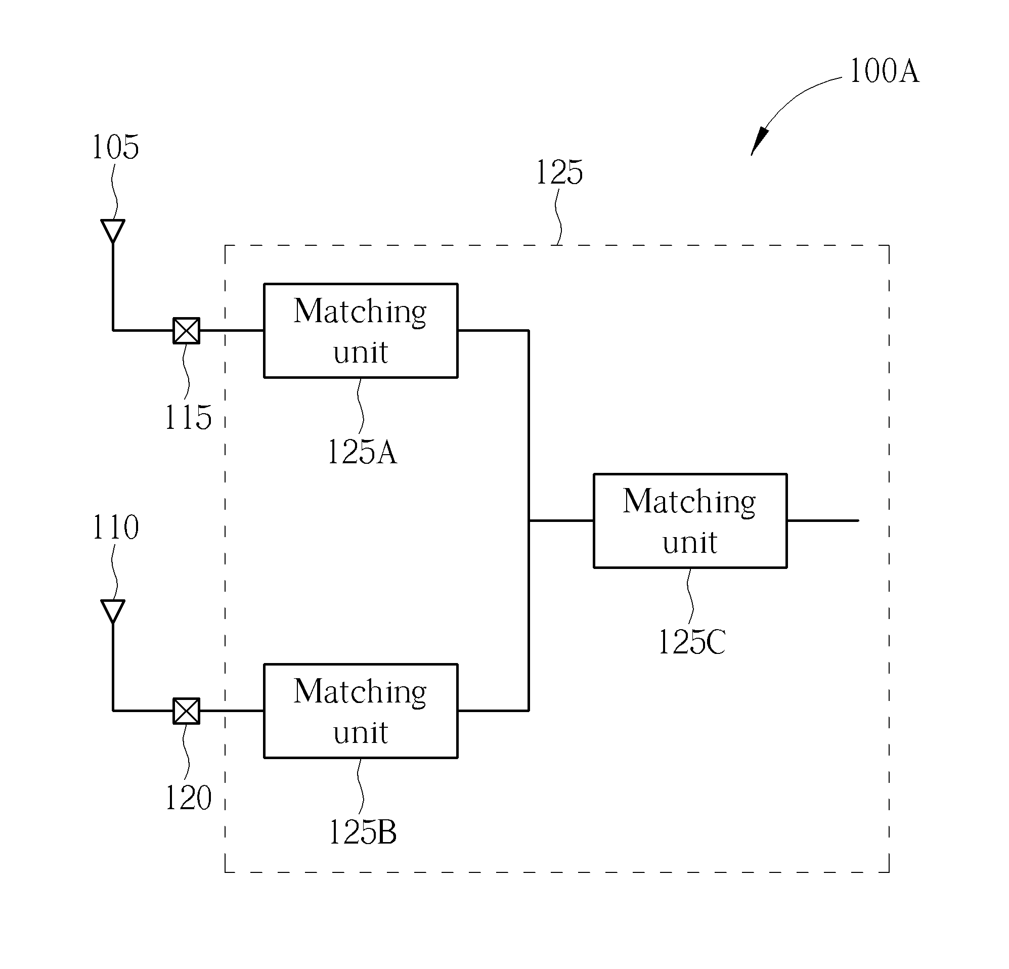
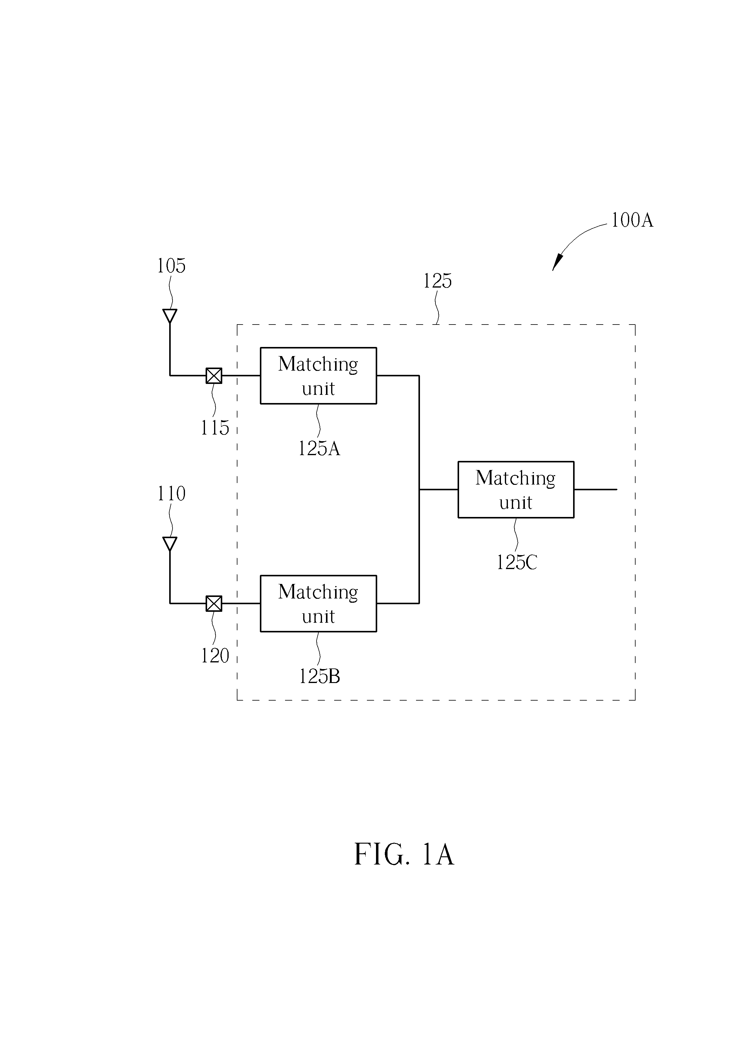
[0017]Please refer to FIG. 1A, which is a block diagram of a portable communication apparatus 100A according to the present invention. As shown in FIG. 1A, the portable communication apparatus 100A comprises a first antenna radiator 105, a second antenna radiator 110, a first feeding point 115, a second feeding point 120, and a matching circuit 125. The first antenna radiator 105 is utilized for radiating / emitting or receiving a high-frequency band signal and the second antenna radiator 110 is utilized for radiating / emitting or receiving a low-frequency band signal. The first feeding point 115 is coupled to the first antenna radiator 105 and utilized for processing feed-in or feed-out of a signal of the first antenna radiator 105. In other words, the first feeding point 115 is used for processing the feed-in and feed-out of the high-frequency band signal. When the portable communication apparatus 100A receives the high-frequency band signal, the first feeding point 115 is arranged t...

second embodiment

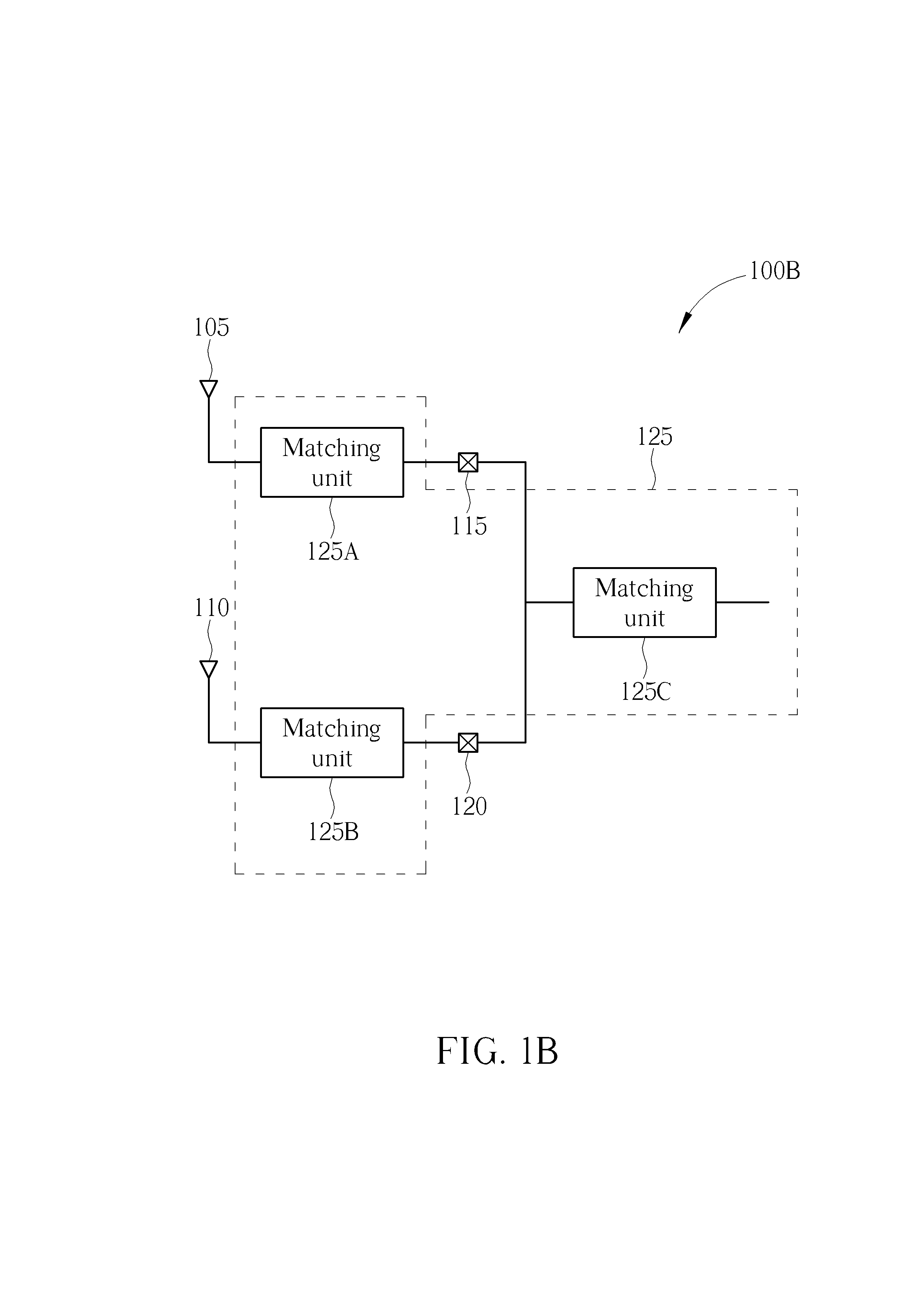
[0022]In another embodiment of the present invention, in practice, a portion of the matching circuit can be included within the antenna body. For example, the matching unit 125A shown in FIG. 1A is not necessarily installed on a circuit board; instead, the matching unit 125A may be used with the first antenna radiator 105 to form the antenna body used for receiving or emitting the high-frequency band signal. Similarly, the matching unit 125B as shown in FIG. 1A is also not necessarily installed on the circuit board; instead, the matching unit 125B may be used with the second antenna radiator 110 to form the antenna body used for receiving or emitting the low-frequency band signal. The matching units 125A and 125C also form a set of effective matching circuits to be matched with the impedance of the first antenna radiator 105 that is used for processing the high-frequency band signal. The matching units 125B and 125C also form a set of effective matching circuits to be matched with t...


PUM


Abstract

A portable communication apparatus includes a first antenna radiator, a second antenna radiator, a first feeding point, a second feeding point, and a matching circuit. The first antenna radiator is used for radiating a high-frequency band signal. The second antenna radiator is used for radiating a low-frequency band signal. The first feeding point is coupled to the first antenna radiator and is utilized for processing feed-in or feed-out of the signal of first antenna radiator. The second feeding point is coupled to the second antenna radiator and is utilized for processing feed-in or feed-out of the signal of second antenna radiator. The first feeding point is separate from the second feeding point. The matching circuit is coupled to the first and second feeding points, and used for impedance matching with the first antenna radiator and the second antenna radiator.

Description

BACKGROUND OF THE INVENTION[0001]1. Field of the Invention[0002]The present invention relates to a scheme of a portable communication apparatus, and more particularly to a portable communication apparatus which uses a separate antenna design.[0003]2. Description of the Prior Art[0004]In a traditional communication device, different antennas respectively used for high-frequency and low-frequency band signals are installed on the same surface or at a same side, so as to save surface area of the communication device. The correlation coefficient between the antennas will become very high, however, when the antennas are installed on the same surface. This higher correlation coefficient causes the whole circuit size of antennas to become very large. A very large circuit size for antenna implementation will cause more restrictions when implementing other appliances of a traditional portable communication apparatus. In addition, the higher correlation coefficient also results in poor commun...

Claims


Application Information

Patent Timeline
Patent Type & Authority Applications(United States)
IPC IPC(8): H01Q21/30H01Q5/10
CPCH01Q5/335H01Q21/30H04B1/0458H04B1/18
Inventor HSIEH, SHIH-WEILIN, CHO-YI
Owner TCL CHINA STAR OPTOELECTRONICS TECH CO LTD
Why Eureka
Try Eureka