Split cage for rolling bearing and rolling bearing using the split cage

a technology of rolling bearing and cage, which is applied in the direction of mechanical equipment, rotary machine parts, engine components, etc., can solve the problems of difficult formation of synthetic resin cages with a large diameter and adverse effects on the performance of rolling bearings, and achieve the effect of preventing abnormal wear of cage segments

Inactive Publication Date: 2013-11-28
JTEKT CORP
View PDF12 Cites 13 Cited by
  • Summary
  • Abstract
  • Description
  • Claims
  • Application Information

AI Technical Summary

Benefits of technology

[0009]One object of the invention is to provide a split cage for a rolling bearing, configured to prevent abnormal wear of cage segments due to relative movement between the adjacent cage segments in the radial direction, and to provide a rolling bearing that uses the split cage.

Problems solved by technology

However, it is difficult to form the synthetic resin cage with a large diameter, as a single-piece member, by injection molding.
As a result, the cage segments 100 may vibrate in the radial direction or the performance of the rolling bearing may be adversely affected by wear debris.

Method used


Image

  • Split cage for rolling bearing and rolling bearing using the split cage
  • Split cage for rolling bearing and rolling bearing using the split cage
  • Split cage for rolling bearing and rolling bearing using the split cage

Examples


Embodiment Construction

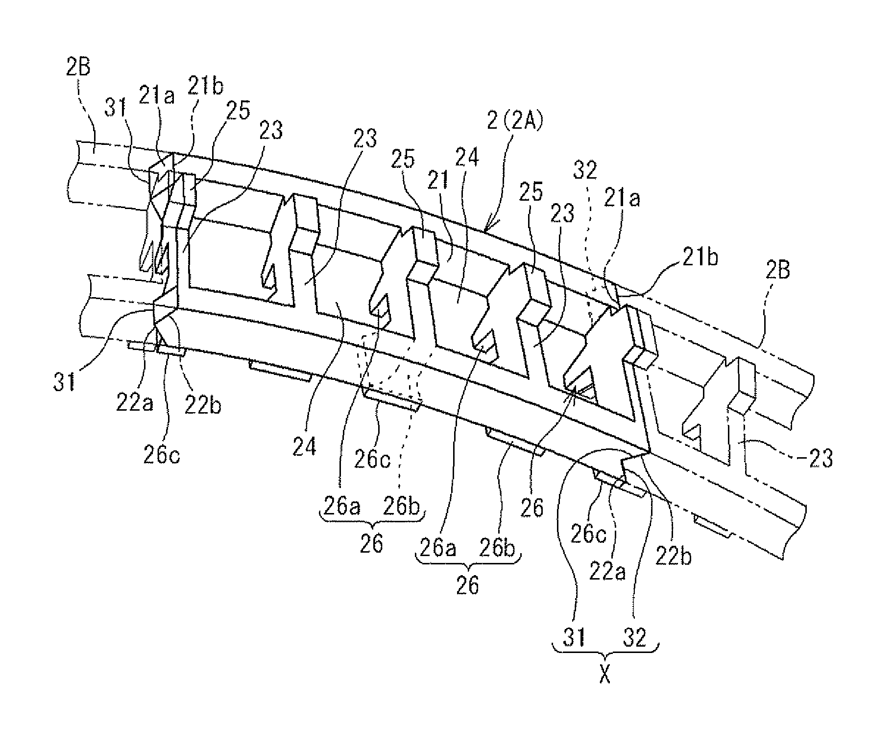
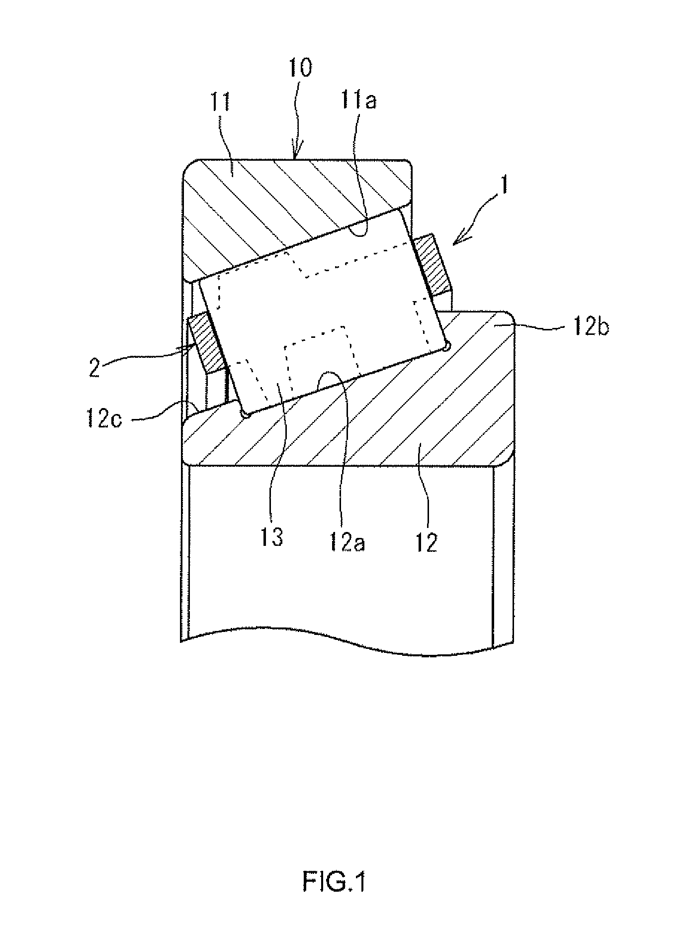
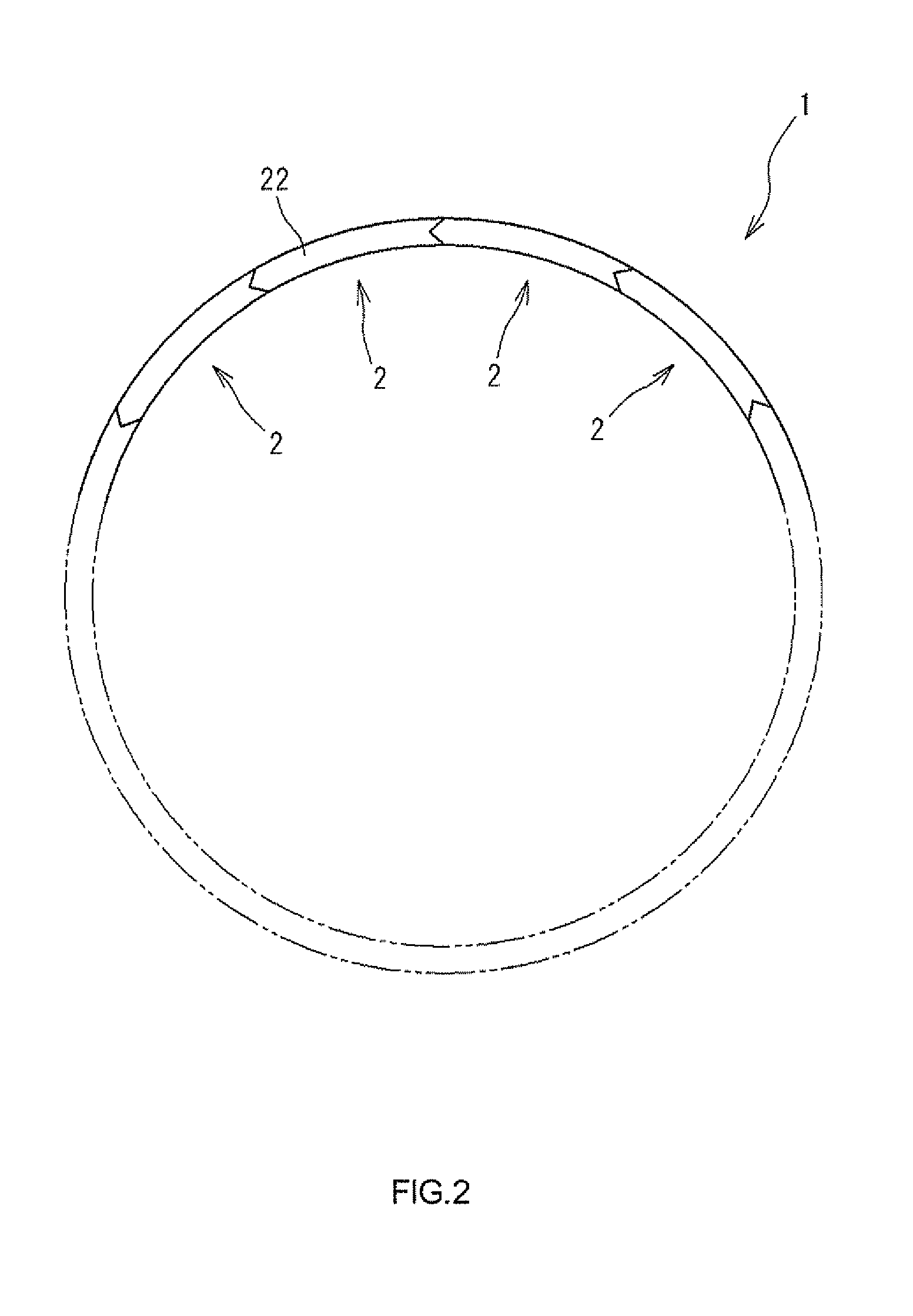
[0020]Hereinafter, embodiments of the invention will be described in detail with reference to the accompanying drawings. FIG. 1 is a sectional view showing main portions of a tapered roller bearing 10 that may function as a rolling bearing according to an embodiment of the invention. The tapered roller bearing 10 is a large-sized tapered roller bearing used to support a main shaft of a wind power generator. In the tapered roller bearing 10, a plurality of tapered rollers 13, which may function as a plurality of rolling elements, is arranged between an outer ring 11 and an inner ring 12. Each of the tapered rollers 13 is held by a split cage 1 that is formed of a plurality of cage segments 2. On the inner periphery of the outer ring 11, an outer ring raceway surface 11 a on which each of the tapered rollers 13 rolls is formed. On the outer periphery of the inner ring 12, an inner ring raceway surface 12a on which each of the tapered rollers 13 rolls is formed. At respective end porti...


PUM


Abstract

In a split cage for a rolling bearing, cage segments each having a plurality of pockets that accommodate rolling elements are arranged in a circular manner along the circumferential direction. Protrusions are formed on end faces of rims of one of the adjacent cage segments, and grooves are formed in end faces of rims of the other one of the adjacent cage segments. By fitting the protrusions into the grooves, the adjacent cage segments are prevented from moving relative to each other in the radial direction.

Description

INCORPORATION BY REFERENCE[0001]The disclosure of Japanese Patent Application No. 2012-116524 filed on May 22, 2012 including the specification, drawings and abstract, is incorporated herein by reference in its entirety.BACKGROUND OF THE INVENTION[0002]1. Field of the Invention[0003]The invention relates to a split cage for a rolling bearing, in which a plurality of cage segments is arranged in a circular manner, and relates also to a rolling bearing using the split cage.[0004]2. Description of Related Art[0005]Conventionally, in a horizontal axis propeller-driven wind power generator, a rolling bearing is used so that a main shaft to which blades are attached is rotatably supported. In recent years, wind power generators have become larger, and accordingly the diameter of a main shaft of a wind power generator may be several meters or more. Accordingly, rolling bearings have become larger in order to support such a large-sized main shaft. As a cage for a large-sized rolling bearing...

Claims


Application Information

Patent Timeline
Patent Type & Authority Applications(United States)
IPC IPC(8): F16C33/56
CPCF16C33/56F16C19/364F16C33/513F16C2300/14F16C2360/31F16C33/4635
Inventor MIYACHI, TAKESHI
Owner JTEKT CORP
Why Eureka
Try Eureka