Method For Profiling A Laid Rail And Processing Vehicle

a technology of processing vehicle and track rail, which is applied in the direction of railway tracks, milling equipment, copying process control systems, etc., can solve the problems of long shut-down time, longer disruption of railway traffic, and natural wear of rails laid in tracks, so as to achieve the exact positioning of machining tools. , the effect of easy operation

Active Publication Date: 2013-12-05
LINSINGER MASCHENBAU GES
View PDF5 Cites 3 Cited by
  • Summary
  • Abstract
  • Description
  • Claims
  • Application Information

AI Technical Summary

Benefits of technology

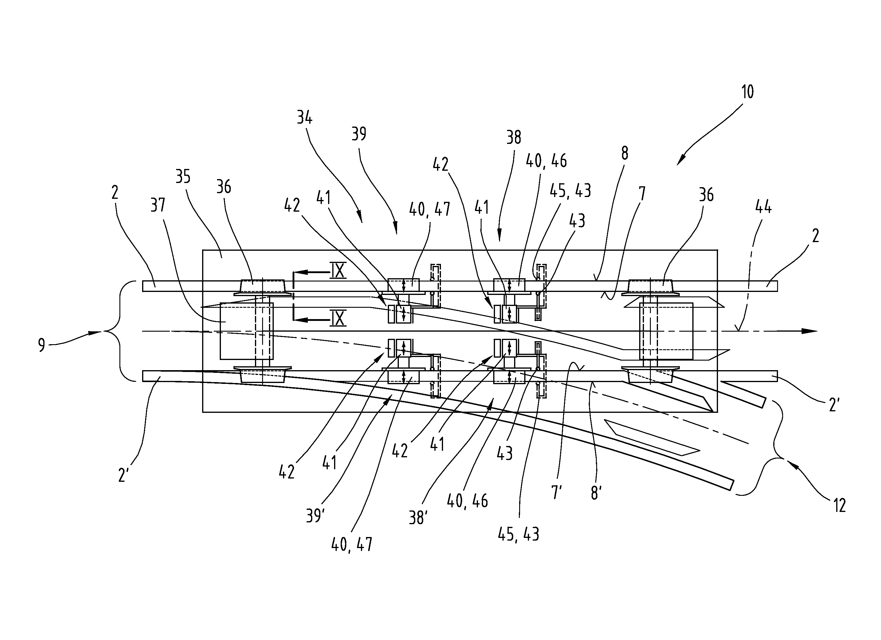
[0021]As defined in the claims, the machining units can preferably be adjusted by means of CNC-controlled shafts, thereby making it easier to obtain an exact positioning of the machining tools. To this end, the shafts have suitable displacement drives, such as servo-motors, for example. The displacement is obtained by appropriate guides, at least in the vertical direction, to enable the machining tools to be moved into engagement and out of engagement with a rail, although it would also be possible to make provision for an additional displacement in the horizontal direction transversely to the rail longitudinal direction, in which case a coupling is provided between the copying probe element and machining tool via the control system. The horizontal displacement is preferably obtained by means of a horizontal guide and a mechanical coupling of the machining unit to the respective copying probe element.
[0022]An embodiment as defined in the claims is of advantage because the processing vehicle has its own drive motor and is not dependent on a towing vehicle and therefore lends itself to universal use.

Problems solved by technology

Rails laid in a track are naturally subject to wear, which is mainly caused by the contact forces acting between the rails and the wheels of the rail vehicles moved on them.
Although the desired profile of rails can be rapidly restored in a rational manner with such a method and such a processing vehicle, it has only been possible to use them on continuous sections of track in the past, whereas the re-profiling of track sections with interruptions, such as in the region of switches or crossings, is often done using hand-held processing tools or smaller special devices, which means that the re-profiling of tracks in the region of switches or crossings still results in longer shut-down times due to the high element of manual labor and thus longer-lasting disruption to railway traffic, running up correspondingly high costs as a result.

Method used


Image

  • Method For Profiling A Laid Rail And Processing Vehicle
  • Method For Profiling A Laid Rail And Processing Vehicle
  • Method For Profiling A Laid Rail And Processing Vehicle

Examples


Embodiment Construction

[0035]Firstly, it should be pointed out that the same parts described in the different embodiments are denoted by the same reference numbers and the same component names and the disclosures made throughout the description can be transposed in terms of meaning to same parts bearing the same reference numbers or same component names. Furthermore, the positions chosen for the purposes of the description, such as top, bottom, side, etc., relate to the drawing specifically being described and can be transposed in terms of meaning to a new position when another position is being described. Individual features or combinations of features from the different embodiments illustrated and described may be construed as independent inventive solutions or solutions proposed by the invention in their own right.

[0036]All the figures relating to ranges of values in the description should be construed as meaning that they include any and all part-ranges, in which case, for example, the range of 1 to 1...


PUM

PropertyMeasurementUnit
widthaaaaaaaaaa
distanceaaaaaaaaaa
timeaaaaaaaaaa

Abstract

The invention relates to a method of profiling a running surface of a laid rail by means of a processing vehicle, in particular in the region of a switch, comprising placing a first copying probe element displaceable transversely to the rail in contact with the running edge or the inner side edge and machining the rail.

Description

BACKGROUND OF THE INVENTION[0001]The invention relates to a method of profiling a track rail as well as a track-guided processing vehicle as defined in the claims.BRIEF SUMMARY OF THE INVENTION[0002]Rails laid in a track are naturally subject to wear, which is mainly caused by the contact forces acting between the rails and the wheels of the rail vehicles moved on them. The undesirable changes which occur in the rail cross-section are treated by a re-profiling method on a regular basis or as and when required in order to lengthen their service life. Re-profiling is primarily done using a machining process involving the removal of material, such as grinding, planing or milling, and these machining processes can be carried out either with the rails dismantled or in the laid track by means of track-guided processing vehicles.[0003]One method of re-profiling a rail is known from WO 02 / 06587 A1, for example. It discloses a track-guided processing vehicle, by means of which the running su...

Claims


Application Information

Patent Timeline
Patent Type & Authority Applications(United States)
IPC IPC(8): E01B31/12E01B31/17E01B31/13
CPCE01B31/12E01B31/13E01B31/17B24B19/004Y10T29/49618Y10T29/49748Y10T29/49778Y10T29/5176Y10T29/54Y10T409/301624Y10T409/30336Y10T409/303472Y10T409/306384Y10T409/30644Y10T409/306496B23C1/20B23C3/005B23C2215/32B23P6/00B23Q9/0007B23Q9/0014B23Q35/04
Inventor KNOLL, JOHANN
Owner LINSINGER MASCHENBAU GES
Why Eureka
Try Eureka