Sensor unit and motion measurement system using the same
a technology of motion measurement and sensor unit, which is applied in the direction of speed measurement using gyroscopic effects, instruments, surveying and navigation, etc., can solve the problems of unwanted shock and vibration for measuring the motion of the measuring target, and the inability to disclose the structure to install the sensor portion,
- Summary
- Abstract
- Description
- Claims
- Application Information
AI Technical Summary
Benefits of technology
Problems solved by technology
Method used
Image
Examples
first embodiment
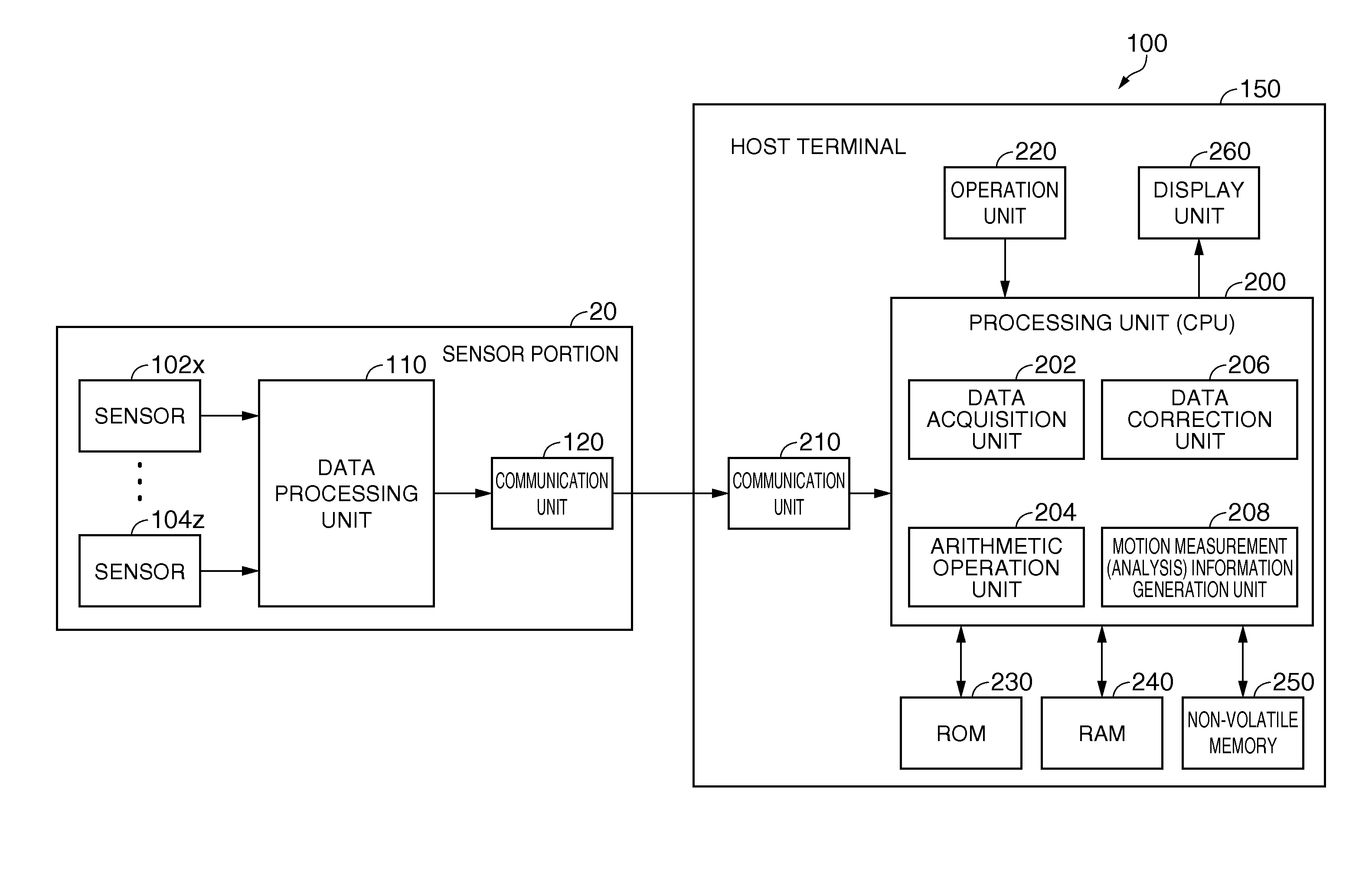
[0044]FIG. 4 is a sectional view schematically showing a cross section of a sensor unit according to a first embodiment of the invention. A sensor unit 10a according to the first embodiment shown in FIG. 4 provides a sensor portion 20 and a buffer body 30.
[0045]The sensor portion 20 provides a three-axis acceleration sensor and a three-axis angular velocity sensor, and a drive circuit and a signal processing circuit for the sensors, for example, installed on face and back sides of a substrate 22a. The maximum acceleration that can be measured by the sensor portion 20 is, for example, 50 G.
[0046]The buffer body 30 provides a first buffer portion 30a and a second buffer portion 30b. The first buffer portion 30a provides a first base portion 34a and a first outer wall 32a extending from the first base portion 34a. The second buffer portion 30b provides a second base portion 34b, a second outer wall 32b extending from the second base portion 34b, and a holding portion 36 at one end oppo...
second embodiment
[0067]A sensor unit 10b according to a second embodiment of the invention is shown in FIG. 10. The sensor unit 10b shown in FIG. 10 is different from the sensor unit 10a shown in FIG. 4 in that a part of the first outer wall 32a and a part of the second outer wall 32b of the buffer body 30 extend respectively and the first buffer portion 30a and the second buffer portion 30b are jointed together in a box-joint form. Hereinafter, different features from the sensor unit 10a according to the first embodiment are described, whereas the same configurations are denoted by the same reference numerals and the description thereof is partly omitted.
[0068]The sensor unit 10b provides a sensor portion 20 and a buffer body 30, similarly to the sensor unit 10a according to the first embodiment. The buffer body 30 provides a first buffer portion 30a and a second buffer portion 30b made of different materials from each other. The buffer body 30 also provides a housing portion 50 that is surrounded ...
third embodiment
[0073]A sensor unit 10c according to a third embodiment is shown in FIG. 11. The sensor unit 10c shown in FIG. 11 is different from the sensor unit 10a shown in FIG. 4 in that the housing portion 50 having a void is filled with a filler 60. Different features from the sensor unit 10a according to the first embodiment are described, whereas the same configurations are denoted by the same reference numerals and the description thereof is partly omitted.
[0074]The filler 60 fills the gap between a first outer wall 32a, a second outer wall 32b, a first base portion 34a and a second base portion 34b, and a sensor portion 20. In other words, the filler 60 fills the void of the housing portion 50 in which the sensor portion 20 is provided. As the filler 60, a member that solidifies after filling the void is used. In this embodiment, for example, a potting material such as trade name TSE3051 (TANAC Co., Ltd.) or trade name 1230G (ThreeBond Co., Ltd.) can be preferably used as the filler 60.
[...
PUM
 Abstract
Description
Claims
Application Information
 - R&D
- Intellectual Property
- Life Sciences
- Materials
- Tech Scout
- Unparalleled Data Quality
- Higher Quality Content
- 60% Fewer Hallucinations
Browse by: Latest US Patents, China's latest patents, Technical Efficacy Thesaurus, Application Domain, Technology Topic, Popular Technical Reports.
© 2025 PatSnap. All rights reserved.Legal|Privacy policy|Modern Slavery Act Transparency Statement|Sitemap|About US| Contact US: help@patsnap.com


