Eureka AIR delivers breakthrough ideas for toughest innovation challenges, trusted by R&D personnel around the world.

Cutting unit of a hydromecanical slot perforator

Active Publication Date: 2013-12-05
KUZYAEV SALAVAT ANATOLYEVICH MR
View PDF17 Cites 8 Cited by
  • Summary
  • Abstract
  • Description
  • Claims
  • Application Information

AI Technical Summary

Benefits of technology

The invention proposed in this patent improves the speed, quality, and uniformity of opening a production string, resulting in better performance punch. It also reduces the likelihood of fractures and strains of perforator's moving parts, as well as cutting tool wear. Additionally, it improves the reliability of the perforator. The device's design is simple, making it reliable and easy to manufacture.

Problems solved by technology

However, when using these devices, the formation of perforated slots is performed only in one projection, which leads to the necessity to reorient the perforator after forming each perforation slot, and to make additional round-trip operations.
The disadvantage of this device is a non-uniform force application on the cutting discs, in virtue of which the upper cutting disc during opening of the column goes beyond its dimensions to the maximum distance, while the lower disc during opening exercises drilling-in less effectively, and therefore the second slot formed by it may not reach required width and depth, and after prolonged use of the perforator and wear of the lower disc can be absent at all.
1. Persisting uneven force application to the cutting disks: force of the piston is primarily applied to the upper blade, and only indirectly to the lower blade.
2. The same quality of column opening by means of both the cutting disks is not provided.
3. Discs are worn unevenly, that after prolonged use leads to an increase in the number of additional round-trip operations necessary to replace the disc.

Method used


Image

  • Cutting unit of a hydromecanical slot perforator
  • Cutting unit of a hydromecanical slot perforator
  • Cutting unit of a hydromecanical slot perforator

Examples


first embodiment

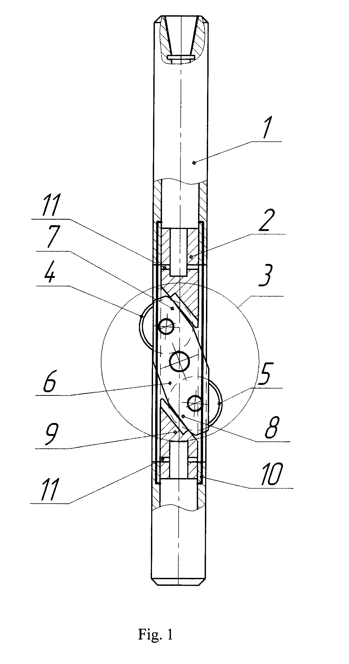
[0038]According to the invention (FIG. 1), a hydro-mechanical slot-type perforator comprises a casing 1, an upper piston 2 placed therein, and a cutting unit 3 located below the piston 2, which cutting unit 3 includes telescoping cutting tools 4, 5 (an upper cutting tool 4 and a lower cutting tool 5), with an extension mechanism in the form of a balance beam 6, having two shoulders 7 and 8, while the cutting tools 4, 5 are mounted respectively in the shoulders 7, 8; at that the balance beam 6 is mounted with the possibility of rotation around an axle during a downward stroke of the upper piston 2 and simultaneous forming of at least two slots in the production column by the cutting tools 4, 5. As shown in FIG. 1, the pistons 2 and 9 preferably have skewed work surfaces providing for efficient cooperation with the respective surfaces of shoulders 7 and 8 receiving pressure from the pistons during contacting therewith. The perforator is equipped with an additional lower piston 9, plac...

second embodiment

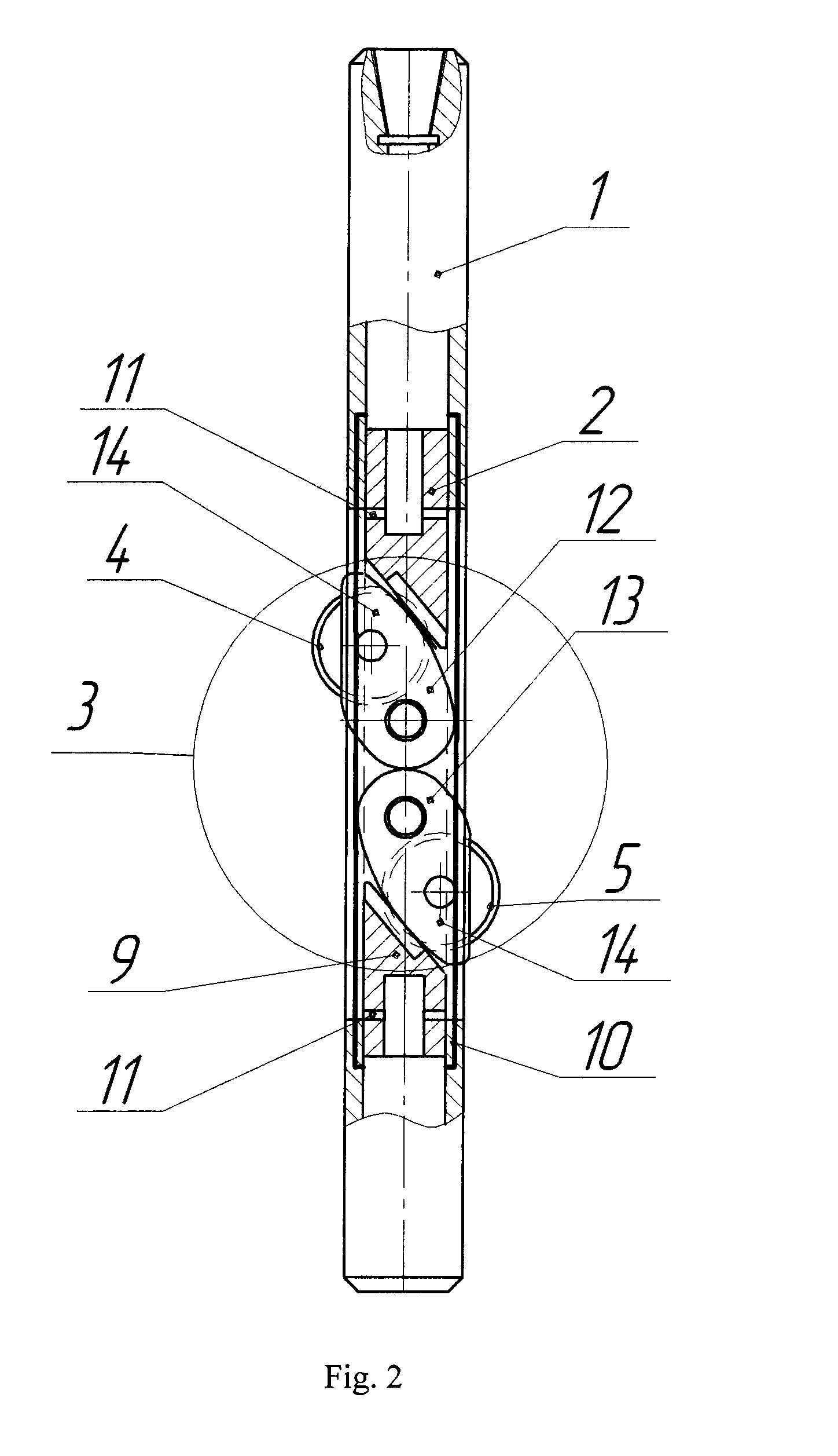
[0039]According to the invention (FIG. 2), the extension mechanism of cutting tools includes an upper shackle 12 and a lower shackle 13; wherein the shackles have movable parts 14, and the shackles 12 and 13 are mounted in the casing 1 with the possibility of rotation of their movable parts 14 under the action of the upper 2 and lower 9 pistons upon these two movable parts respectively. The cutting tools 4, 5 are mounted on the movable parts 14 of the shackles 12, 13 correspondingly.

[0040]The shackles 12 and 13 have respective axles 15 of rotation of their movable parts 14. The axles 15 may be located on the same line, which is perpendicular to the longitudinal axis of the perforator (FIG. 3). The axles 15 may optionally coincide (for example, forming one common axle), while their movable parts 14 can rotate independently (FIG. 4).

third embodiment

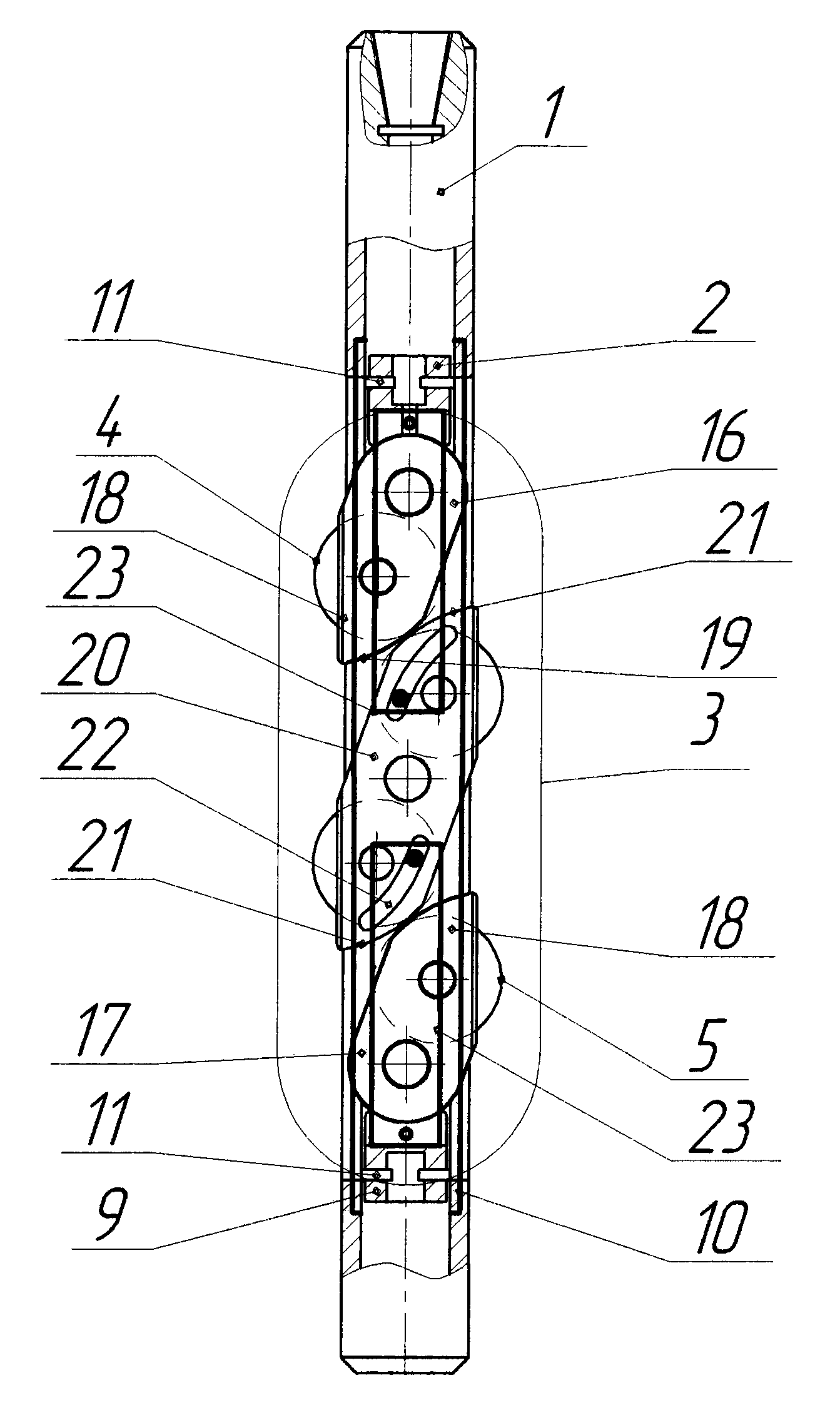
[0041]According to the invention (FIG. 5), the extension mechanism of the cutting tools 4, 5 includes contains an upper wedge-type shackle 16 and a lower wedge-type shackle 17, having movable parts 18; the shackles 16 and 17 are mounted oppositely to each other on the upper piston 2 and on the lower piston 9 respectively, with the possibility of rotation of their movable parts 18; at that the cutting tools 4, 5 are mounted on the oppositely directed movable parts 18 of the shackles 16 and 17. The shackles 16 and 17 have wedge-shaped ending portions 19 (‘V-surfaces’), made with the possibility of interaction and movement relative to each other with the extension of the cutting tools 4 and 5 in opposite directions during a countermotion of the pistons 2, 9.


PUM


Abstract

The proposed hydro-mechanical slot-type perforator enables simultaneously performing at least two slots in a production column. The perforator includes a casing, upper and lower pistons movable within the casing, a cutting unit driven by the pistons and carrying extendable cutting tools, and, optionally, a retractable mechanism fixing the perforator for transportation. The extension is provided by rotatable shackles, or balance beams, or a combination thereof. The lower piston is moved by pressurized fluid supplied through hydraulic channels or a hydraulic system, made in the casing. The shackles rotate around axles being spaced apart, or coincided. The cutting tools can be mounted on the shackles' movable parts, and, when mutually interacted, oppositely extend the cutting tools during countermovement of the pistons. The cutting tools can be mounted in the balance beam's shoulders, or can represent sharp edges thereof. The shackles and balance beams can have wedge-shaped portions, grooves, and connecting rods.

Description

CROSS-REFERENCE TO RELATED APPLICATIONS[0001]This application is a U.S. national stage application of a PCT application PCT / IB2012 / 000230 filed on 9 Feb. 2012, published as WO2012110867, whose disclosure is incorporated herein in its entirety by reference, which PCT application claims priority of a Russian Federation patent application RU2011105450 filed on 14 Feb. 2011.FIELD OF THE INVENTION[0002]The proposed invention relates to drilling and well operations, in particular to the design of devices for the opening of productive formations by hydromechanical slot perforation, and can be used in the construction and repair of wells for various purposes.BACKGROUND OF THE INVENTION[0003]In the prior art, there are known devices for slot perforation of wells disclosed in Russian Federation Patents RU 2205941 C2, IPC 7 E21B 43 / 112, 10.06.2003; RU 2244806 C1, IPC 7 E21B 43 / 112, 20.01.2005; RU 2254451 C1, IPC 7 E21B 43 / 112 , 20.06.2005; RU 2239053 C1, IPC 7 E21B 43 / 114, 27 Oct. 2004, contai...

Claims


Application Information

Patent Timeline
IPC IPC(8): E21B43/112
CPCE21B43/112E21B29/06
Inventor PASVANDI, MARIE
Owner KUZYAEV SALAVAT ANATOLYEVICH MR
Why Eureka
Eureka Blog
Learn More