
Flow rectifier for closed pipelines

a technology of flow rectifier and closed pipeline, which is applied in the direction of fluid dynamics, material analysis using wave/particle radiation, instruments, etc., can solve the problems of high operating cost of a system of this type for disinfecting drinking water, too much energy expended in this area, and low efficiency of slow flow volume elements

Active Publication Date: 2013-12-05
XYLEM IP HLDG
View PDF2 Cites 5 Cited by
  • Summary
  • Abstract
  • Description
  • Claims
  • Application Information

AI Technical Summary

Benefits of technology

The patent text describes a design for a UV reactor that achieves an even speed distribution of gas downstream of a flow rectifier. This is achieved by using an inlet cone with inner and outer guide elements. The invention allows for a larger cross-section of the channel from an incoming pipeline into the reactor, which results in a more even gas velocity distribution. Additionally, the outer guide element can be shaped to match the shape of the inlet cone, allowing for different cross-sectional shapes to achieve the desired speed distribution. Overall, this design improves the efficiency and performance of UV reactors by achieving a more uniform gas velocity distribution.

Problems solved by technology

This means that, with a strongly inhomogeneous flow within the UV reactor, the slowly flowing volume elements receive too high a dosage, i.e. too much energy is expended in this area if the fastest-flowing volume elements are reliably to receive a dosage above the required minimum dosage.
A substantial part of the operating costs of a system of this type for disinfecting drinking water is incurred by the power consumption of the UV radiators which are used.
These baffle plates increase the flow resistance of the system and reduce the possible liquid throughput.

Method used


Image

  • Flow rectifier for closed pipelines
  • Flow rectifier for closed pipelines
  • Flow rectifier for closed pipelines

Examples


tenth embodiment

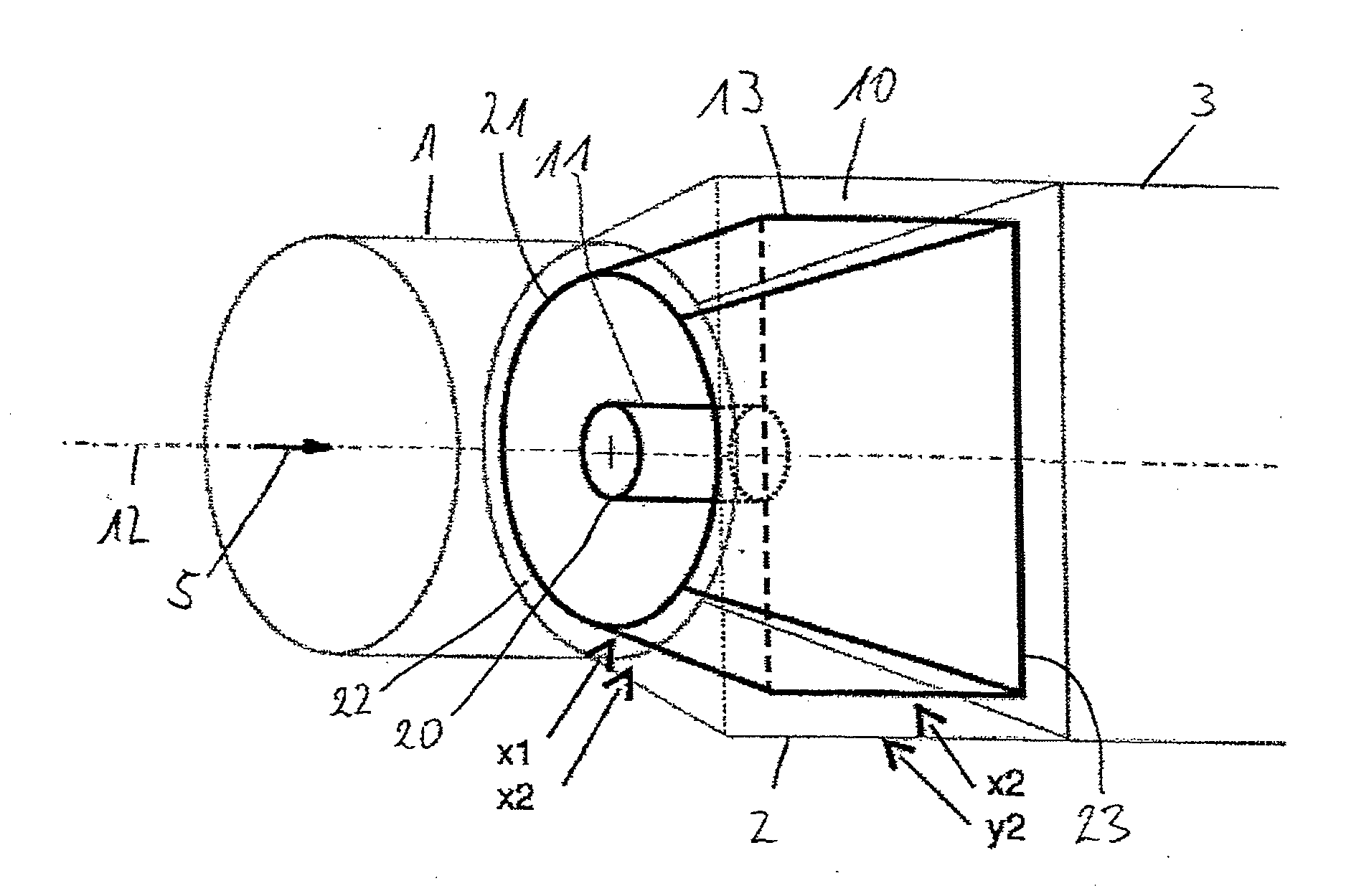
[0052]FIG. 14 shows the present invention. A channel 100 with a constant, circular diameter extends without a transition in the area of a step 101 to a cylindrical area 102 in which the flow rectifier is disposed with the inner guide element 11 and the outer guide element 13. In a further variant, which is shown by dotted lines, the first guide element 11 is extended beyond the area of the second guide element 13. The second guide element 13 is extended by the attachment of a cylindrical guide element 103 in the direction of flow, wherein the guide element 103 has the diameter of the larger end of the second guide element 13.

eleventh embodiment

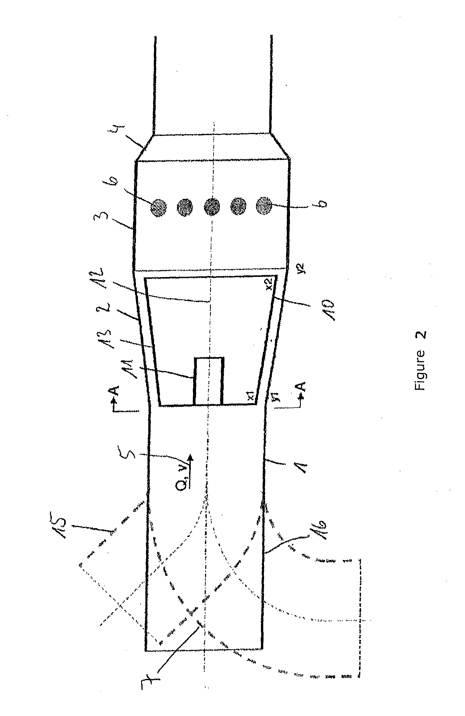
[0053]FIG. 15 shows the present invention. The channel is designed as step-shaped, as illustrated in FIG. 14. An inner guide element 110 has a conical shape with an upstream end with a smaller diameter and a downstream end with a larger diameter. A cylindrical, tubular guide element 111 is connected to the downstream end. A second guide element 112 similarly has a conical shape, but with the larger diameter upstream and the smaller diameter downstream. The upstream end lies in the direction of flow upstream of the transition of the first guide element 110 into the guide element 111. The downstream end of the guide element 112 lies downstream of the guide element 111. A variant is shown by dotted lines. In this variant, an additional cylindrical guide element 114 is provided, which has a constant diameter over its longitudinal extension. The upstream end of the guide element 114, which concentrically surrounds the guide element 112, is disposed between the upstream end and the downst...


PUM


Abstract

A channel for a UV irradiation device, in which the UV irradiation device is disposed in a closed channel and an inlet cone is provided in the direction of flow upstream of a UV reactor, which, as part of the wall of the channel, increases the cross section of the channel from an incoming pipeline cross section to a cross section of the reactor, in which a flow rectifier with at least one inner first guide element and at least one outer second guide element is disposed in the inlet cone, wherein the inner guide element is a substantially circular, cylindrical pipe and the outer guide element runs substantially parallel to the outer wall and is disposed at a distance from the outer wall.

Description

CROSS-REFERENCE TO RELATED APPLICATIONS[0001]This is a U.S. National Phase Patent Application of PCT International Patent Application Number PCT / EP2011 / 003759, filed Jul. 27, 2011, which claims priority benefit of German Patent No. DE 10 2010 047 782.6, filed Oct. 8, 2010, each of which is incorporated herein by reference in its entirety.FIELD OF THE INVENTION[0002]The present invention relates to a flow rectifier for closed pipelines.BACKGROUND OF THE INVENTION[0003]UV irradiation of flowing liquids is undertaken for various purposes, for example to disinfect drinking water and waste water, and to trigger chemical reactions which are enabled by the UV radiation. The UV dosage given to each volume element is always decisive for the desired effect of the UV radiation in the liquid. In disinfection applications, the microorganisms contained in the water are reliably disinfected only if a specific minimum dosage is applied to them. It is therefore necessary to set the radiation power i...

Claims


Application Information

Patent Timeline
Patent Type & Authority Applications(United States)
IPC IPC(8): B01J19/12
CPCB01J19/123C02F1/325C02F2201/3227C02F2201/328C02F2301/022F15D1/001
Inventor ANTON, HANS-JOACHIMRAPAKA, MADHUKAR
Owner XYLEM IP HLDG
Learn More