Piezoelectric vibrating piece and piezoelectric device

a piezoelectric device and vibrating piece technology, applied in piezoelectric/electrostrictive/magnetostrictive devices, piezoelectric/electrostriction/magnetostriction machines, electrical equipment, etc., can solve the problem of reducing the strength of the connecting portion, reducing the impact resistance of the piezoelectric device, and varying the stress transfer from the printed circuit board to the vibrator

Inactive Publication Date: 2013-12-05
NIHON DEMPA KOGYO CO LTD
View PDF1 Cites 4 Cited by
  • Summary
  • Abstract
  • Description
  • Claims
  • Application Information

AI Technical Summary

Problems solved by technology

However, there is a problem that transmission of stress from the printed circuit board to the vibrator varies a characteristic of a vibration frequency of the vibrator.
However, with Patent Literature

Method used


Image

  • Piezoelectric vibrating piece and piezoelectric device
  • Piezoelectric vibrating piece and piezoelectric device
  • Piezoelectric vibrating piece and piezoelectric device

Examples


second embodiment

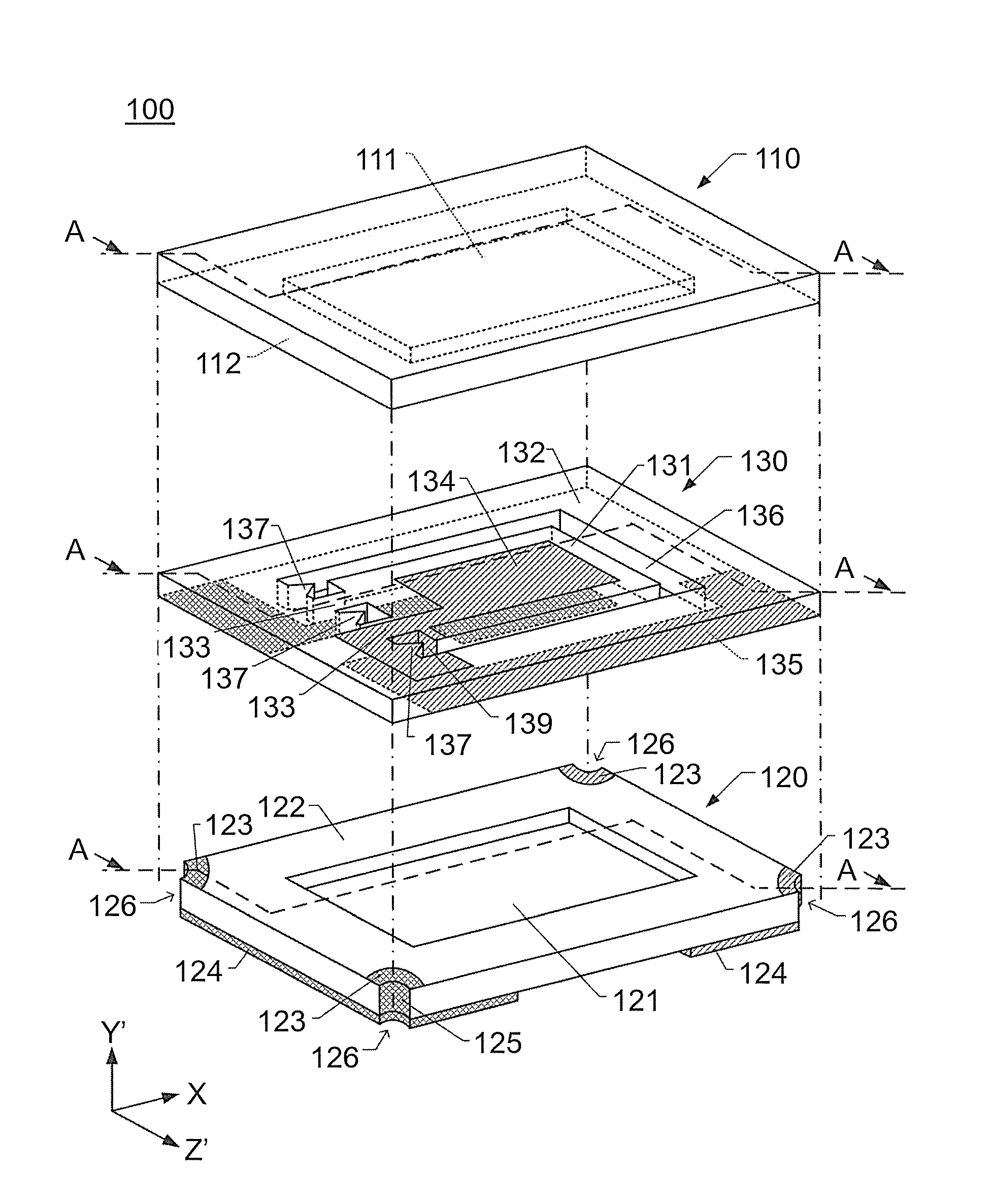
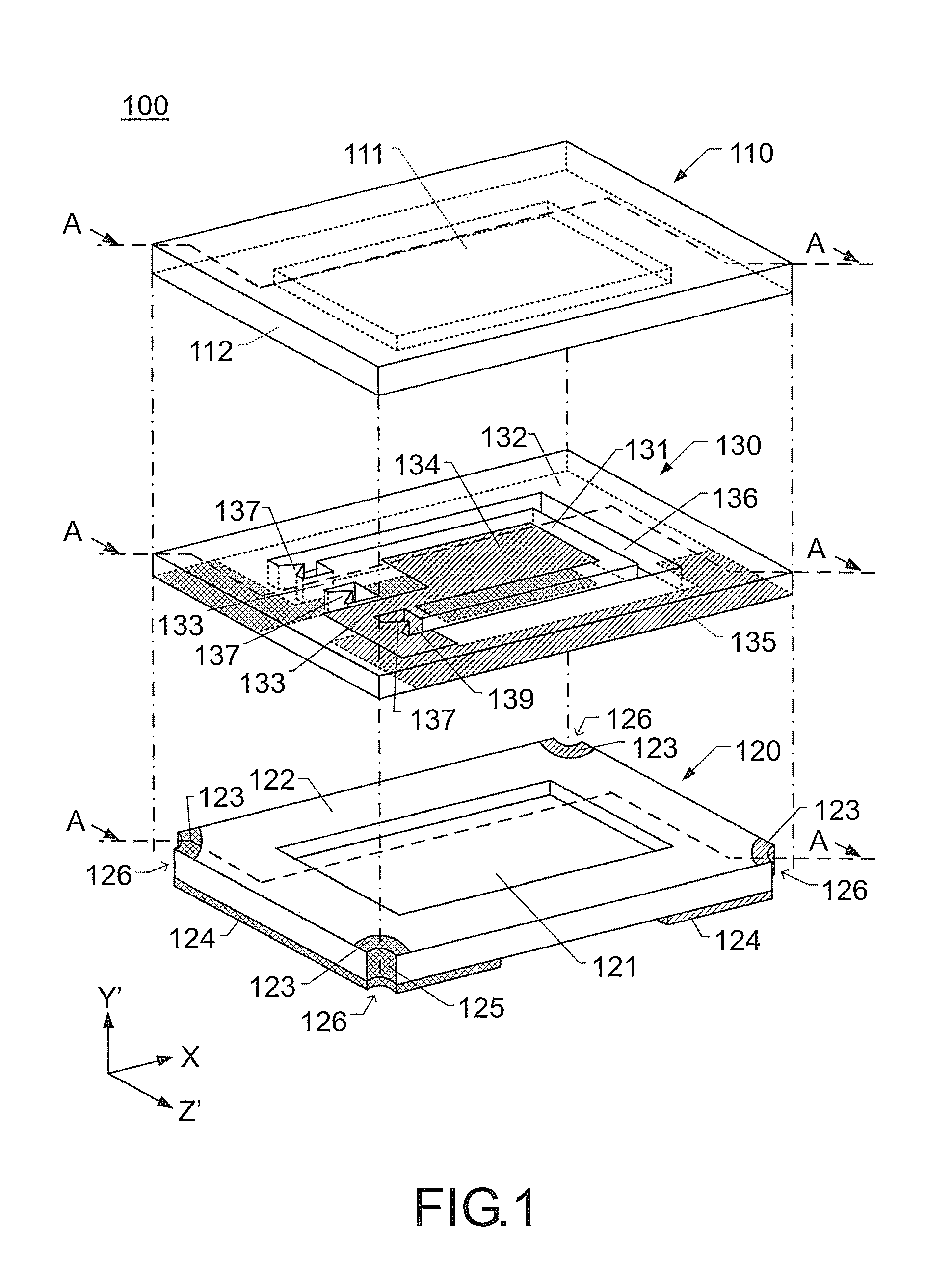
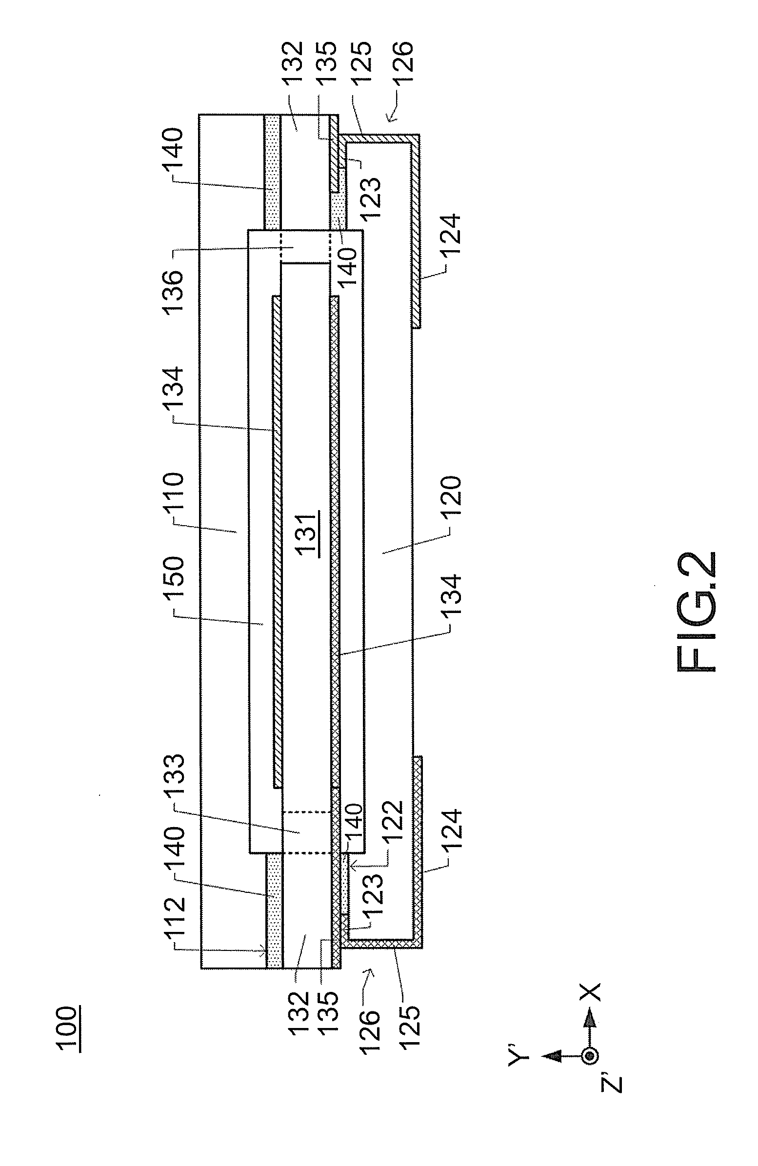
[0033]A piezoelectric vibrating piece may be different from the piezoelectric vibrating piece 130 in a position where the connecting portion is connected, the number of connecting portions, or similar specification. Additionally, a protrusion shape of the protrusion 137 may be different. A description will be given of a piezoelectric vibrating piece 230 to a piezoelectric vibrating piece 730 as a modification of a piezoelectric vibrating piece. Like reference numerals designate corresponding or identical elements throughout the first embodiment and the second embodiment, and therefore such elements will not be further elaborated here.

Constitution of the Piezoelectric Vibrating Piece 230

[0034]FIG. 4(a) is a plan view of the piezoelectric vibrating piece 230 on the surface at the +Y′-axis side. The piezoelectric vibrating piece 230 includes the vibrator 131, the framing portion 132, and one connecting portion 233. In the piezoelectric vibrating piece 230, the connecting portion 233 co...


PUM


Abstract

A piezoelectric vibrating piece includes a rectangular vibrator, a framing portion, a connecting portion, and a protrusion. The rectangular vibrator vibrates at a predetermined vibration frequency. The framing portion surrounds a peripheral area of the vibrator. The framing portion includes an inner side surface facing the vibrator. The connecting portion connects the vibrator and the framing portion. The protrusion protrudes to the vibrator side. The protrusion is formed on at least one of the inner side surface facing a side of the vibrator where the connecting portion is connected and the inner side surface adjacent to the connecting portion.

Description

CROSS REFERENCE TO RELATED APPLICATIONS[0001]This application claims the priority benefit of Japan application serial no. 2012-125544, filed on Jun. 1, 2012. The entirety of the above-mentioned patent application is hereby incorporated by reference herein and made a part of this specification.TECHNICAL FIELD[0002]This disclosure relates to a piezoelectric vibrating piece where a framing portion is formed and a piezoelectric device.DESCRIPTION OF THE RELATED ART[0003]A piezoelectric vibrating piece that includes a vibrator vibrating at a predetermined vibration frequency, a framing portion surrounding the vibrator, and a connecting portion connecting the vibrator and the framing portion is known. A piezoelectric device where a base plate and a lid plate are to be bonded respectively on one principal surface and the other principal surface of a framing portion of a piezoelectric vibrating piece is also known. This piezoelectric device is employed by being mounted to a printed circuit ...

Claims


Application Information

Patent Timeline
IPC IPC(8): H01L41/053
CPCH01L41/053H03H9/1021H03H2003/022H10N30/88
Inventor TAKAHASHI, TAKEHIROMIZUSAWA, SHUICHI
Owner NIHON DEMPA KOGYO CO LTD
Why Eureka
Try Eureka