Photovoltaic device for measuring irradiance and temperature

a photovoltaic device and irradiance technology, applied in the direction of power supply testing, instruments, sustainable buildings, etc., can solve the problems of rarely monitoring array performance and impracticality of weather monitoring stations

Inactive Publication Date: 2013-12-05
DOW GLOBAL TECH LLC
View PDF7 Cites 95 Cited by
  • Summary
  • Abstract
  • Description
  • Claims
  • Application Information

AI Technical Summary

Problems solved by technology

For a residential installation, in which building aesthetics play an important role, such a weather monitoring station is impractical.
Residential monitoring systems, therefore, rarely monitor array performance, only output.

Method used


Image

  • Photovoltaic device for measuring irradiance and temperature
  • Photovoltaic device for measuring irradiance and temperature
  • Photovoltaic device for measuring irradiance and temperature

Examples


Embodiment Construction

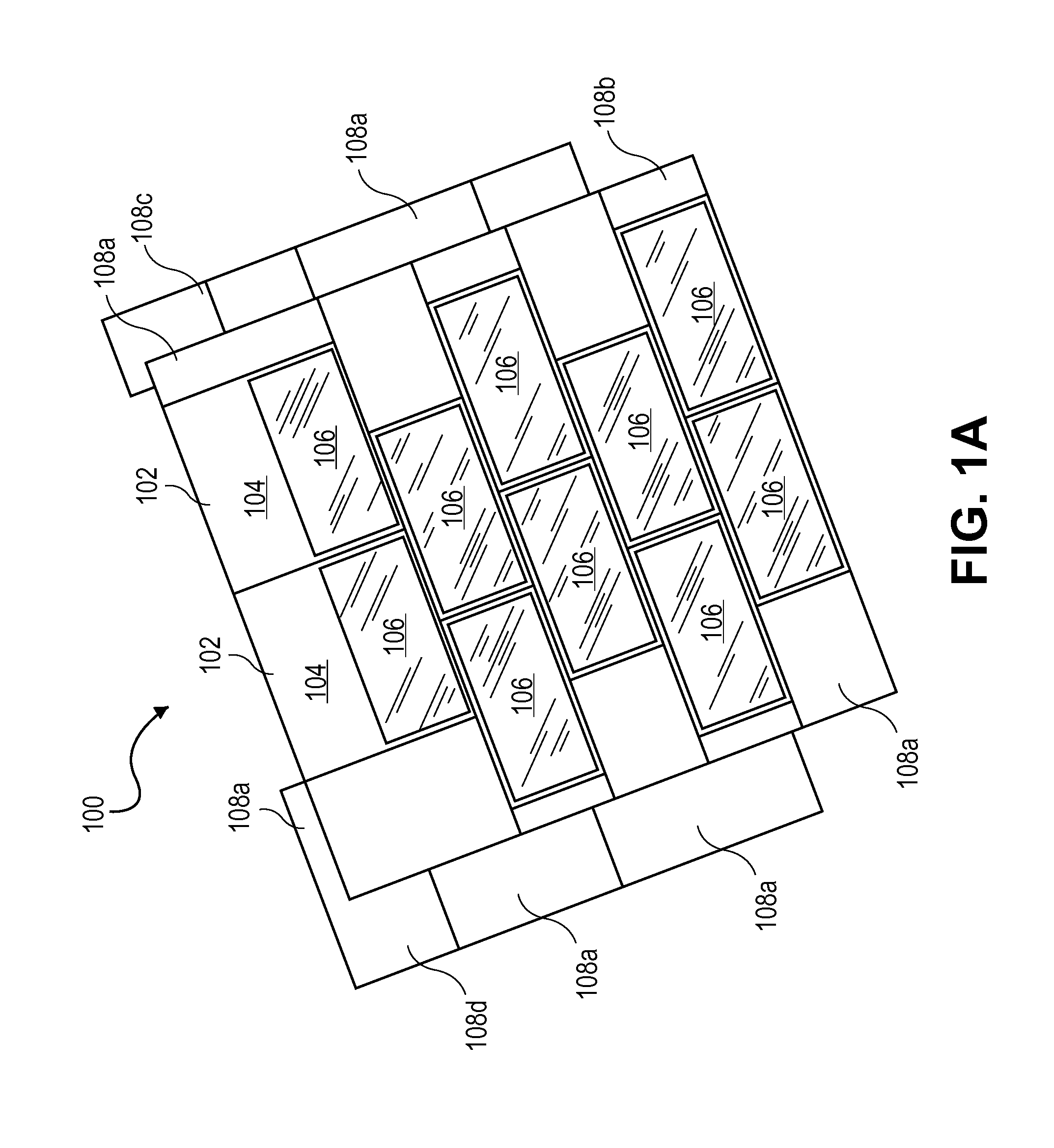
[0015]FIG. 1A depicts an installation of a solar array system 100 which may be used in conjunction with the systems and methods described herein. The system 100 includes a number of building integrated photovoltaic devices 102 that include both a body portion 104 and a photovoltaic cell module 106. The system 100 may include at least one edge piece 108a located at the end or within the at least two rows / columns of photovoltaic devices 102. Additionally, at least one starter piece 108b, at least one filler piece 108c, and at least one end piece 108d may be utilized. These components, as well as elements used for connection of these components, are described in International Publication Number WO 2009 / 137353, the disclosure of which is hereby incorporated by reference herein in its entirety.

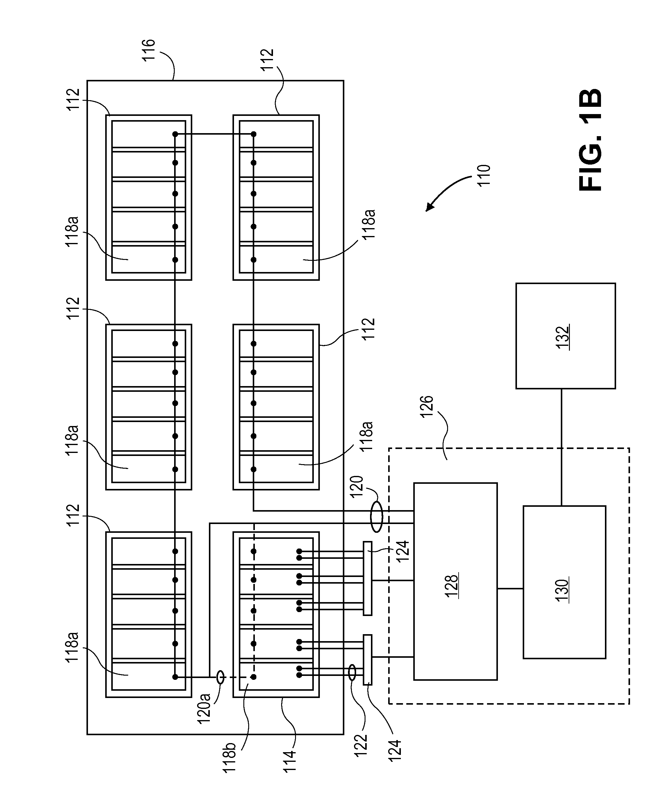
[0016]FIG. 1B depicts an embodiment of a solar array system 110. The solar array system 110 includes a plurality of power-generator modules 112 and one sensor module 114 installed, in this case, on...


PUM


Abstract

A solar array system includes a plurality of power-generator modules, each power-generator module having an identical form factor and comprising a plurality of photovoltaic cells wired for power generation. The system also includes at least one sensor module having a substantially identical appearance and form factor as the power-generator modules and comprising a like plurality of photovoltaic cells. The operational state of the system is monitored by an array performance monitor, which measures signals sent from the various modules. At least one photovoltaic cell in the sensor module delivers a short-circuit current signal to the array performance monitor and at least one photovoltaic cell in the sensor module delivers an open-circuit voltage signal to the array performance monitor. These signals are used to calculate a theoretical power output of the array system, which is compared to the actual power output.

Description

[0001]This application is being filed on 21 Nov. 2011, as a PCT International Patent application in the name of Dow Global Technologies LLC, a U.S. national corporation, applicant for the designation of all countries except the U.S., and, Stephen G. Pisklak, a citizen of the U.S., David L. King, a citizen of the U.S., Michael J. Lesniak, a citizen of U.S., and Narayan Ramesh, a citizen of India, applicants for the designation of the U.S. only, and claims priority to U.S. patent application Ser. No. 61 / 419,136 filed on 2 Dec. 2010, the disclosure of which is incorporated herein by reference in its entirety.INTRODUCTION[0002]The vast majority of solar array monitoring systems currently on the market monitor only the solar array output. These array monitoring systems give no indication of whether or not the solar array is functioning as designed. In order to provide such information, irradiance and module temperature must be measured concurrently and at the same location as the array. ...

Claims


Application Information

Patent Timeline
Patent Type & Authority Applications(United States)
IPC IPC(8): G01R31/40
CPCH02S50/00H02S50/10Y02B10/10Y02E10/50
Inventor PISKLAK, STEPHEN G.KING, DAVID L.LESNIAK, MICHAEL J.RAMESH, NARAYAN
Owner DOW GLOBAL TECH LLC
Why Eureka
Try Eureka